I’ve spent the last couple of months in my spare time designing a button that I don’t really need.
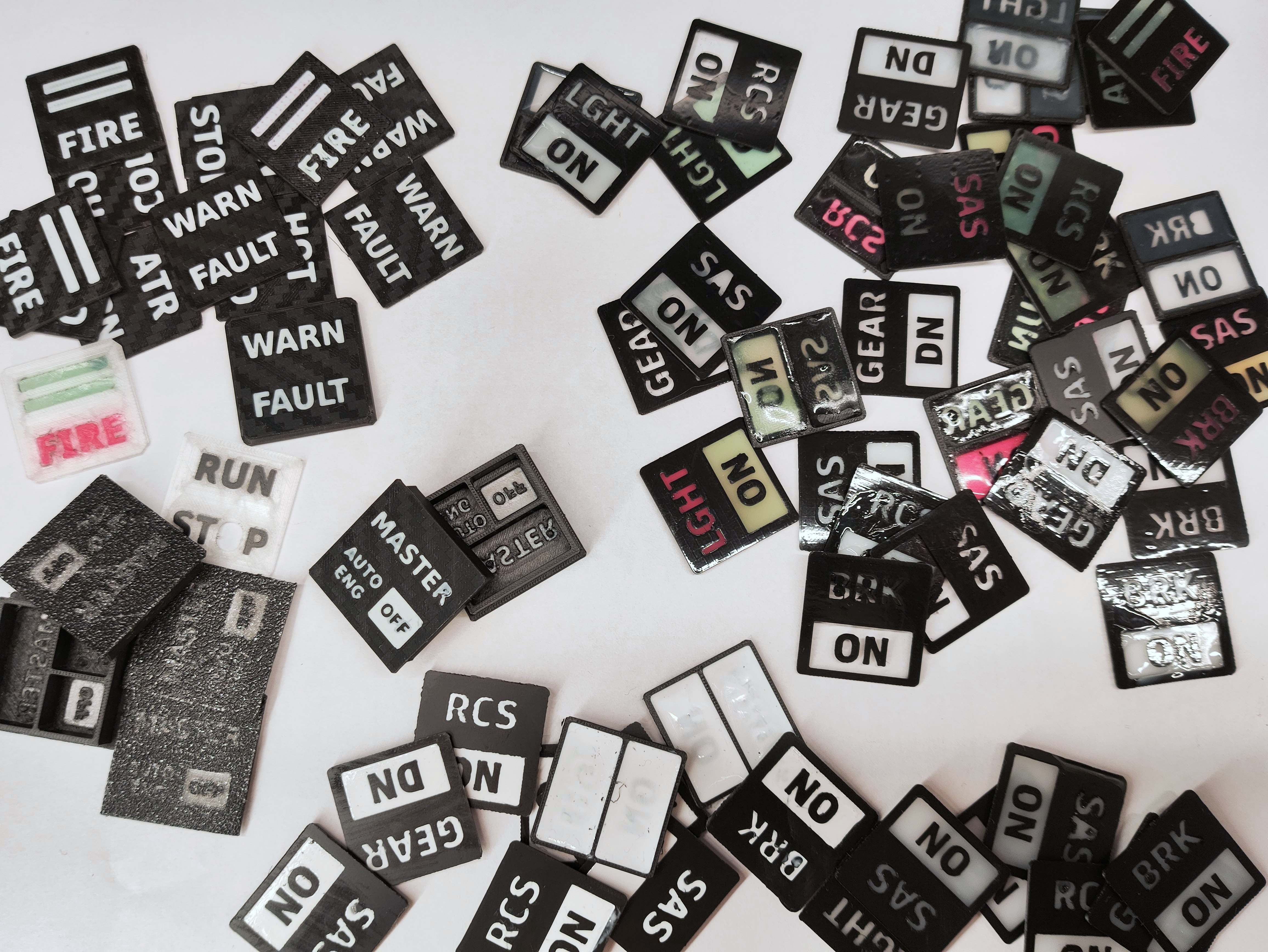
It started out with some experiments to see how small I could print text using the 0.2mm nozzle using the AMS to print in both black and white and it just sort of snowballed from there.
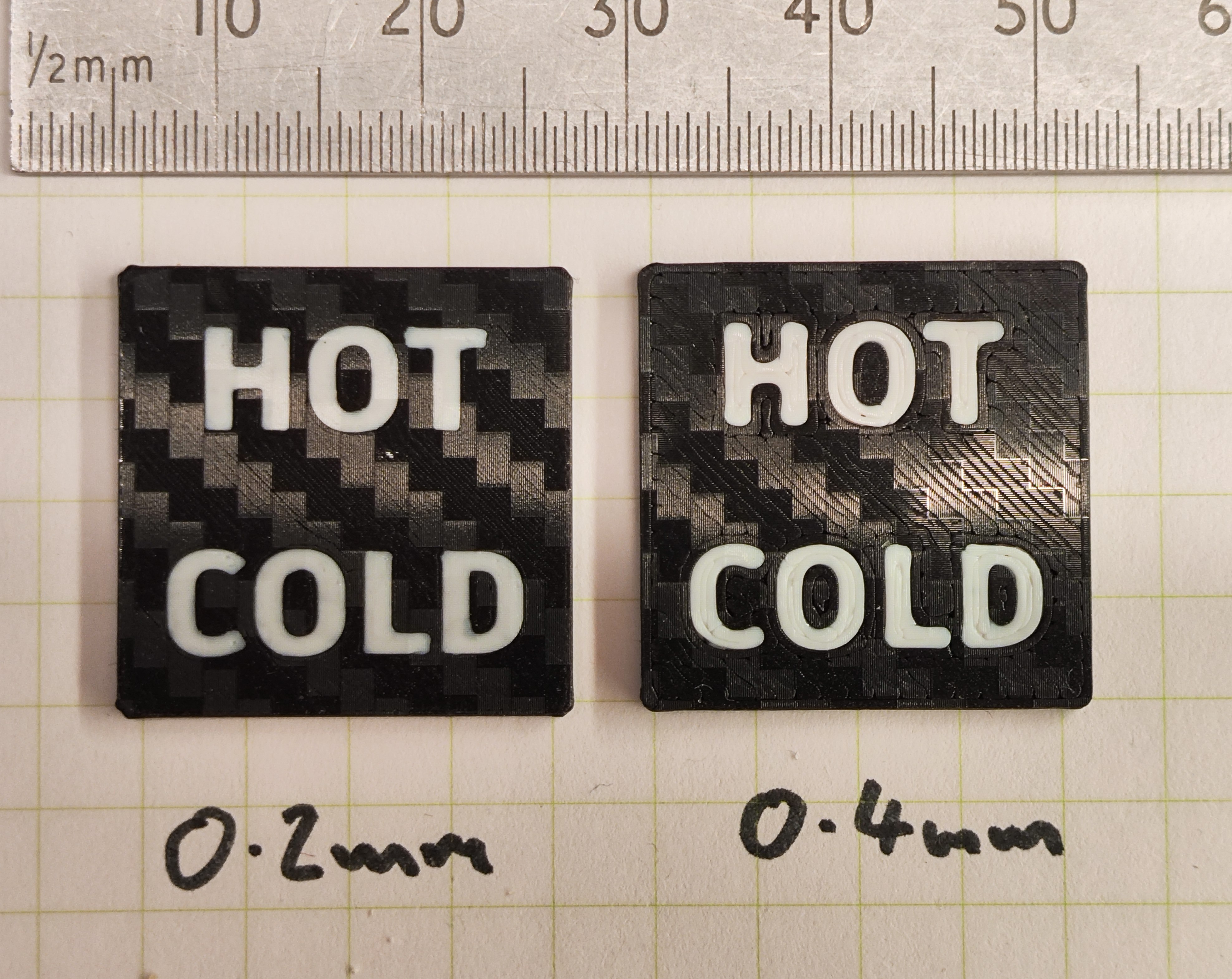
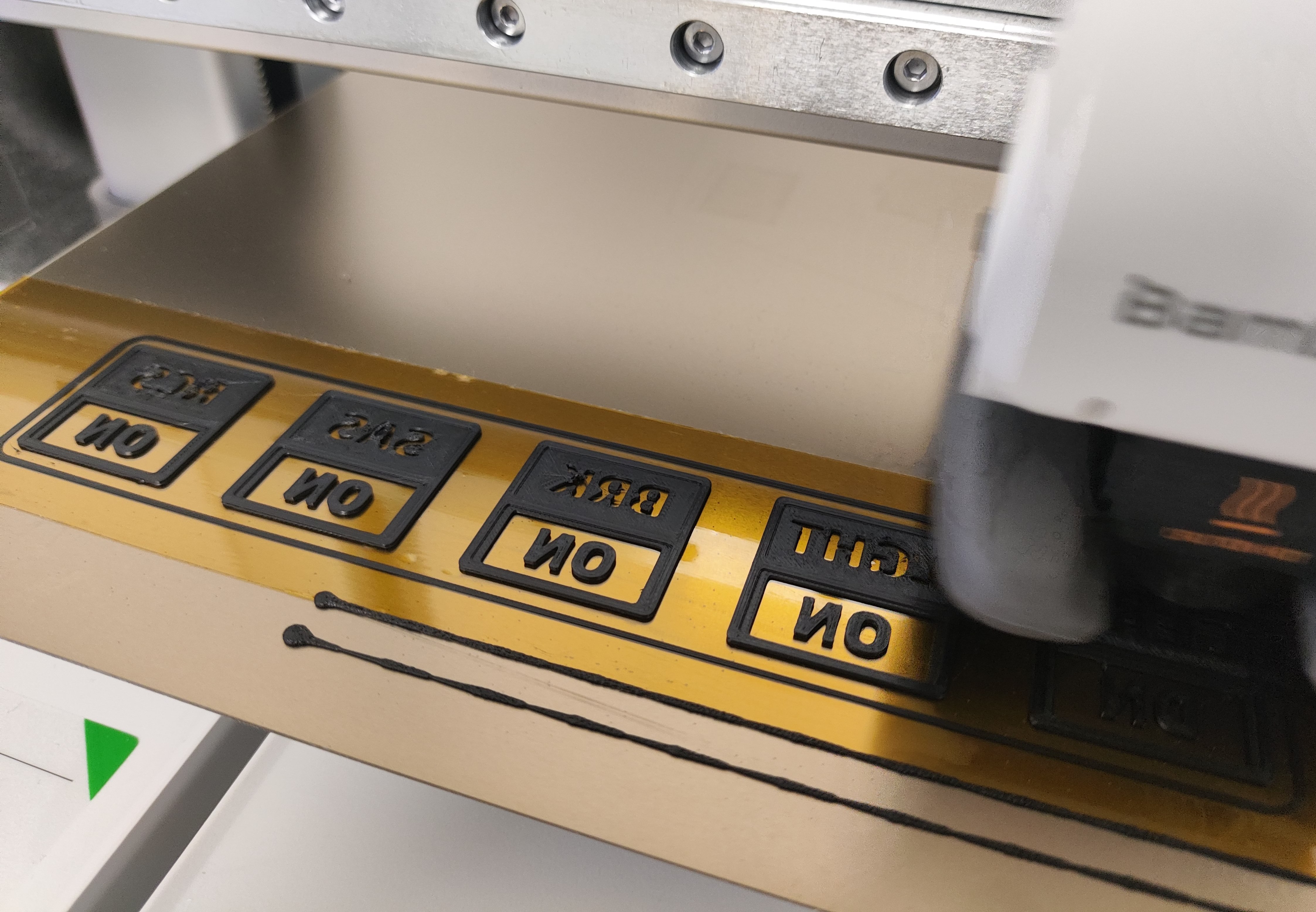
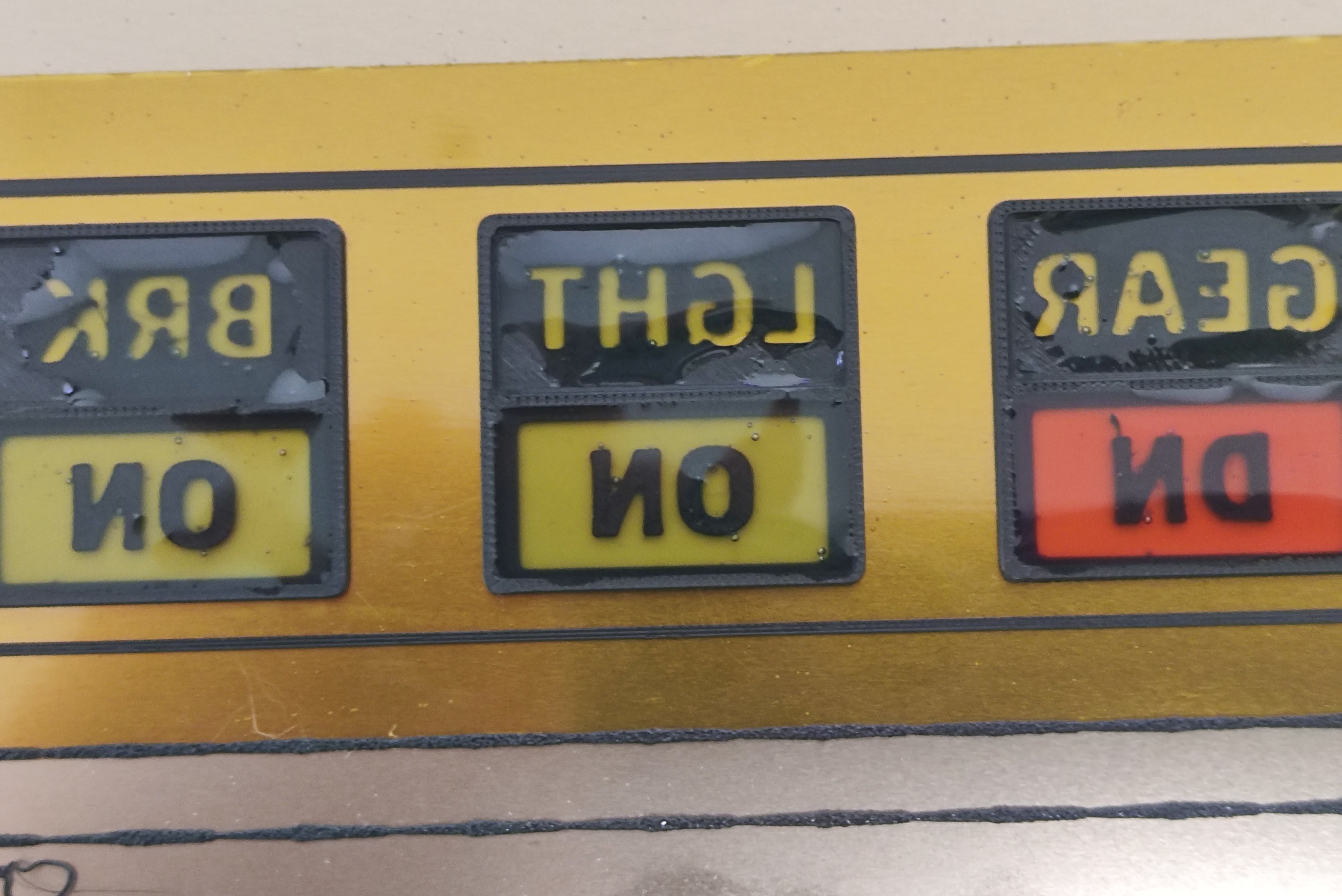
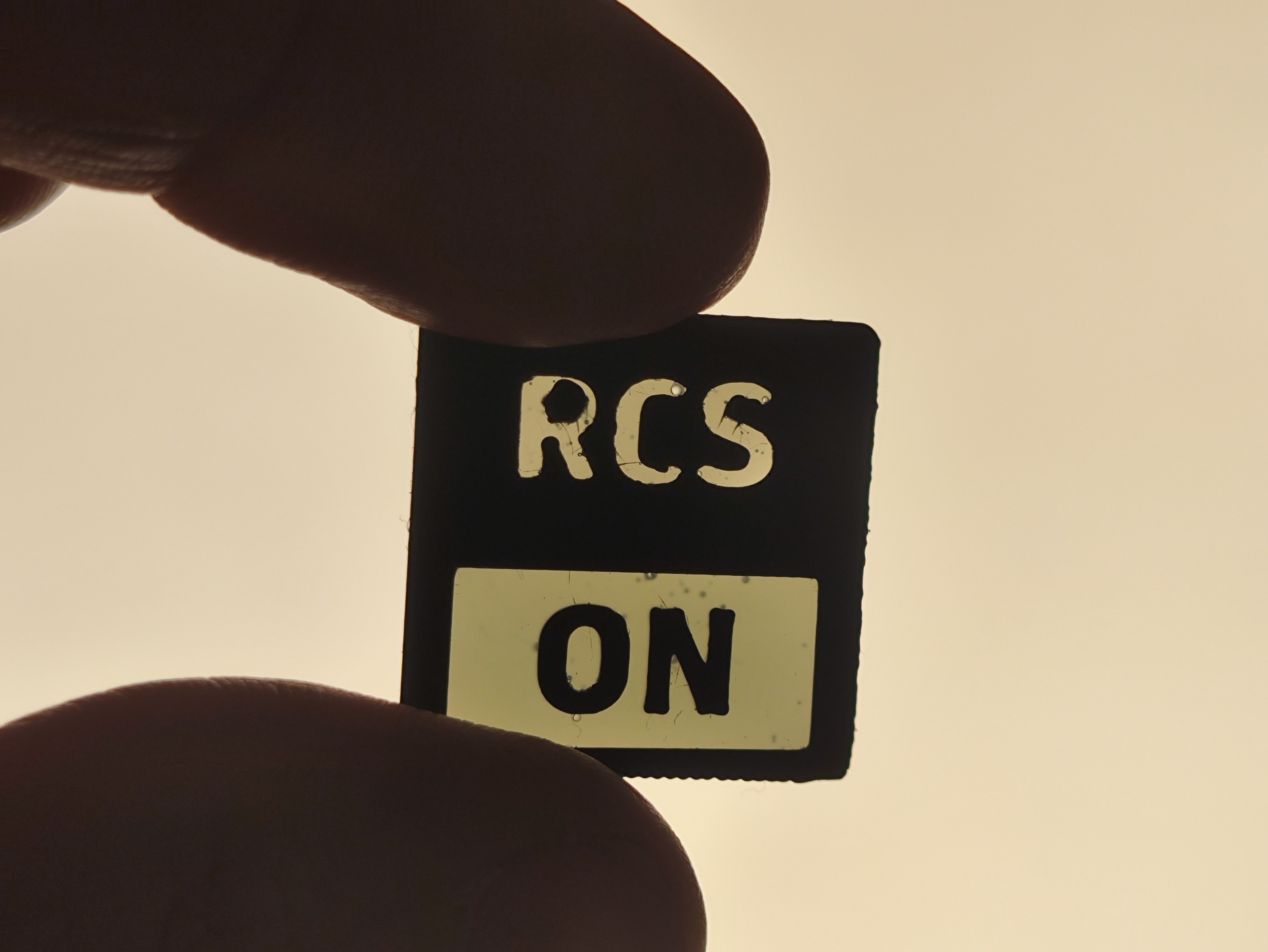
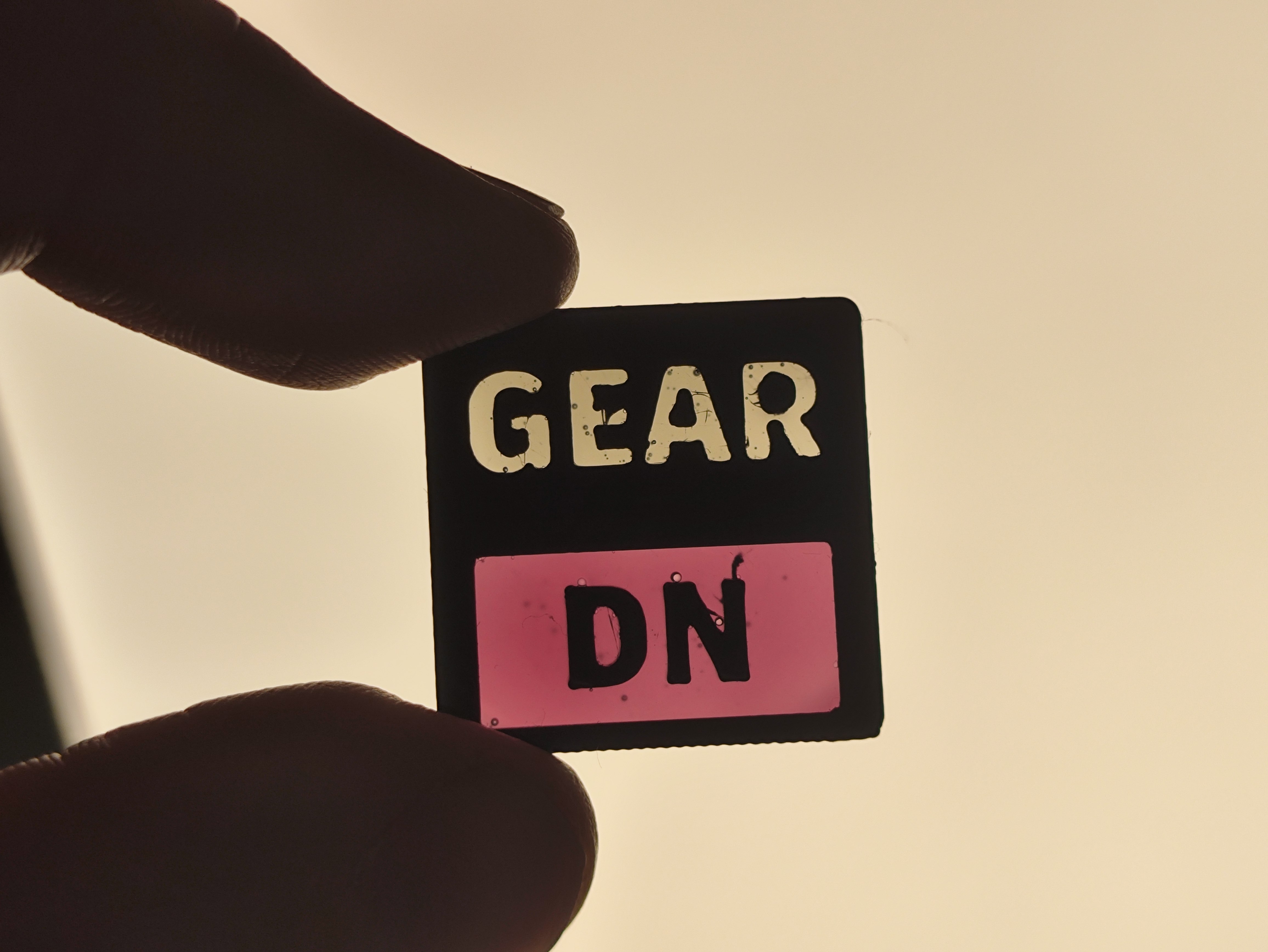
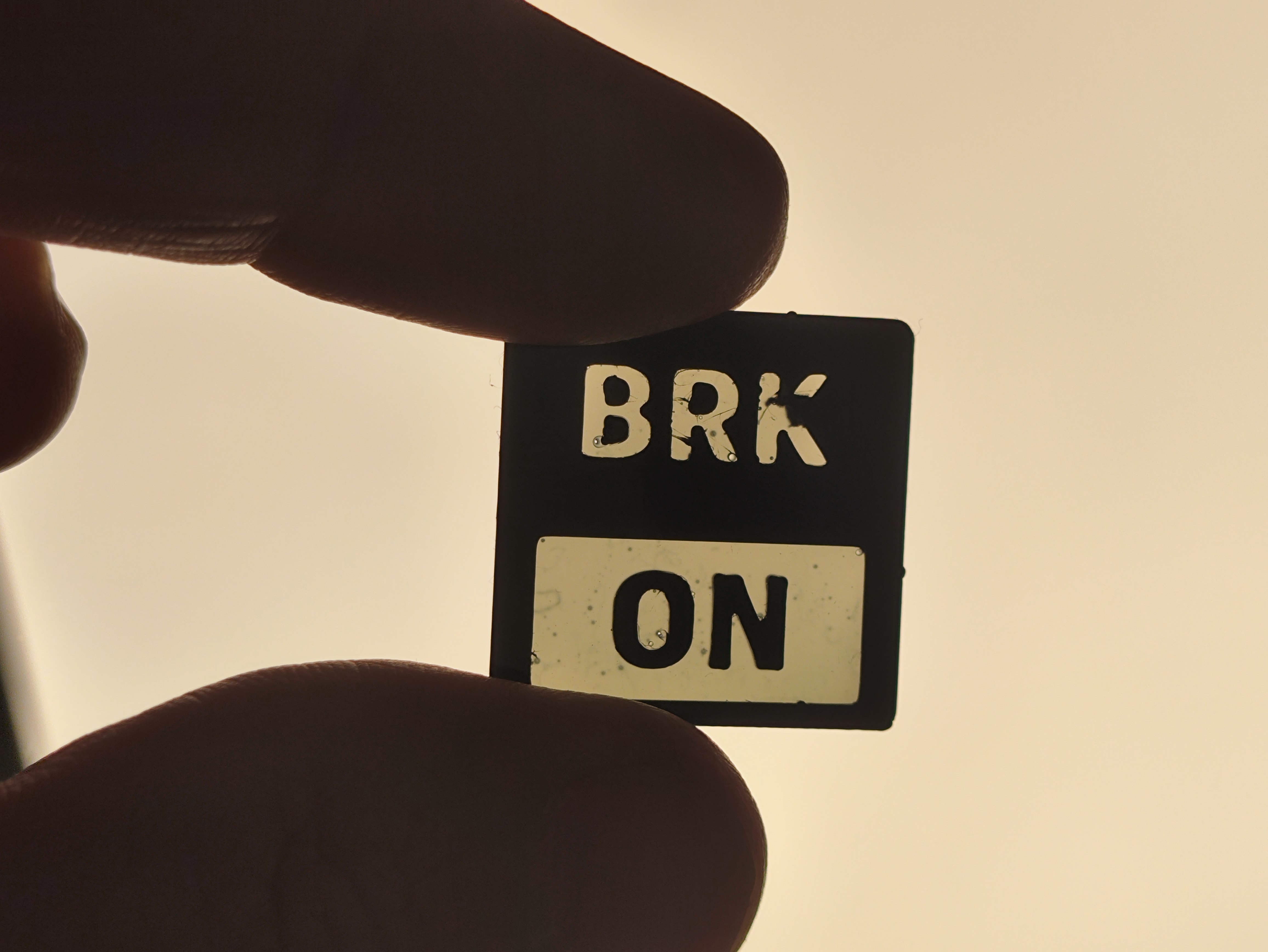
Then I thought, hey those tiles look kinda like those illuminated buttons you have on an aircraft flight deck, I wonder if I print the white really thin it’ll let though any light. So I made some more tests where the white is only 0.3mm thick (3 layers)
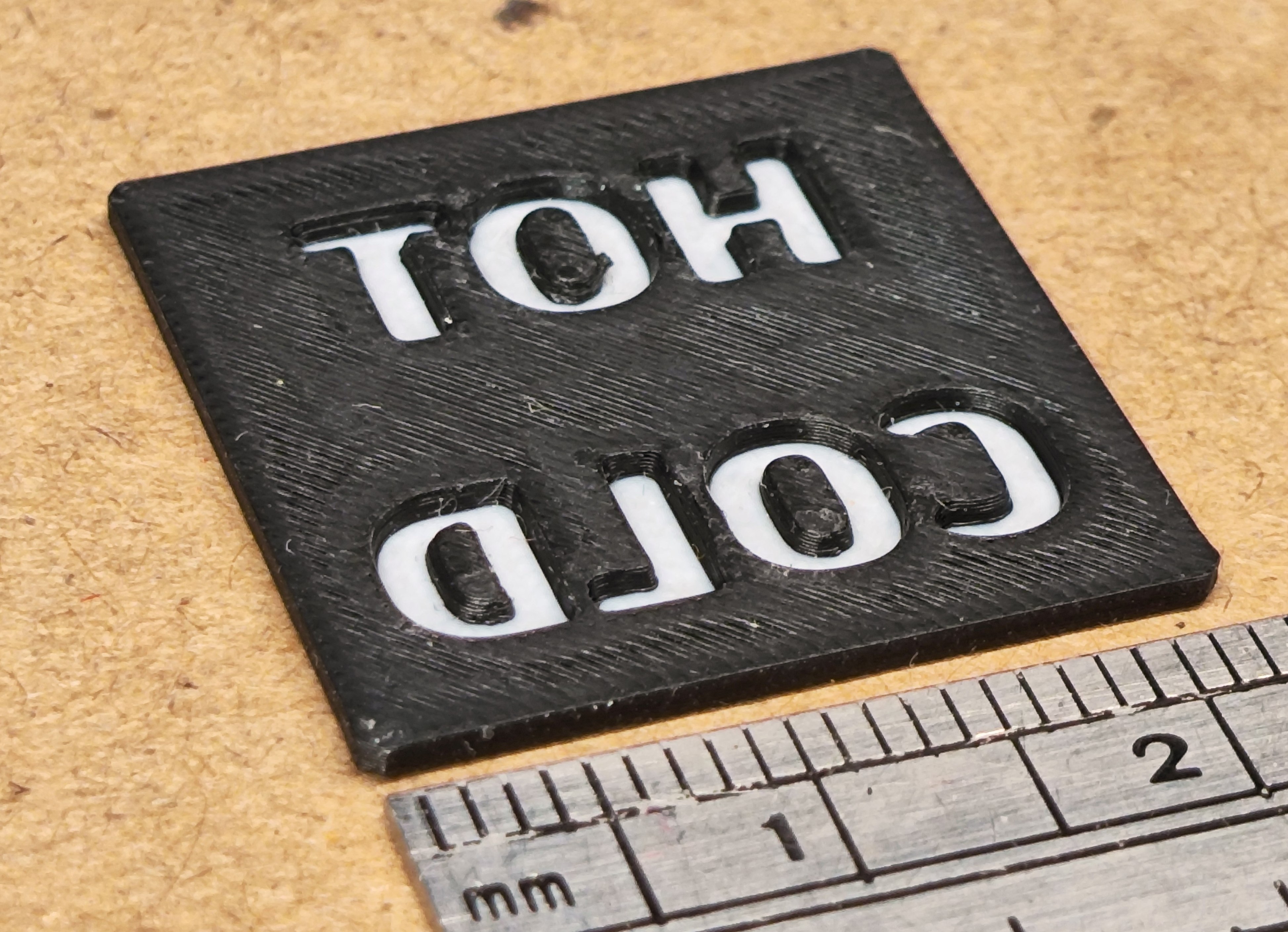
I tried printing with transparent filament but the only stuff I had to hand was PETG and that doesn’t bond well with PLA. The letters would pop out when you lift the print off the bed.
Also whilst multimaterial prints are awesome they are also really, really time consuming. So I thought maybe a better idea would be to print just the black tile shell and fill the voids with something else such as UV resin! Off to aliexpress I went…
In the meantine in Fusion 360
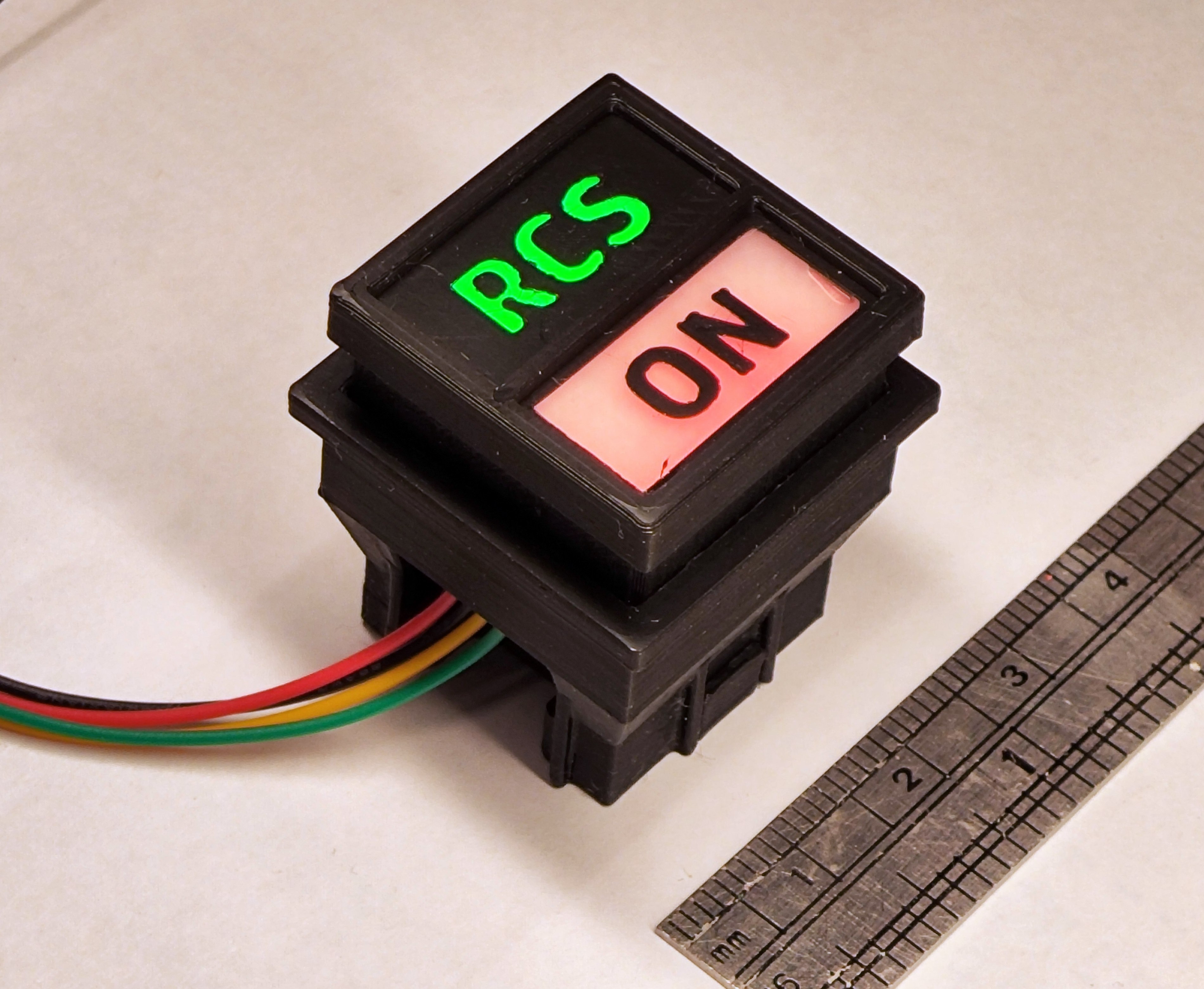
I had an Idea to create some buttons that could be used to play Kerbal Space Program. Years ago I had made a an external navball using a plugin that sends data out via serial and I recalled that you could also send data back in. I thought it might be fun to have a minimal control panel for lights, gear, brakes, SAS and RCS.
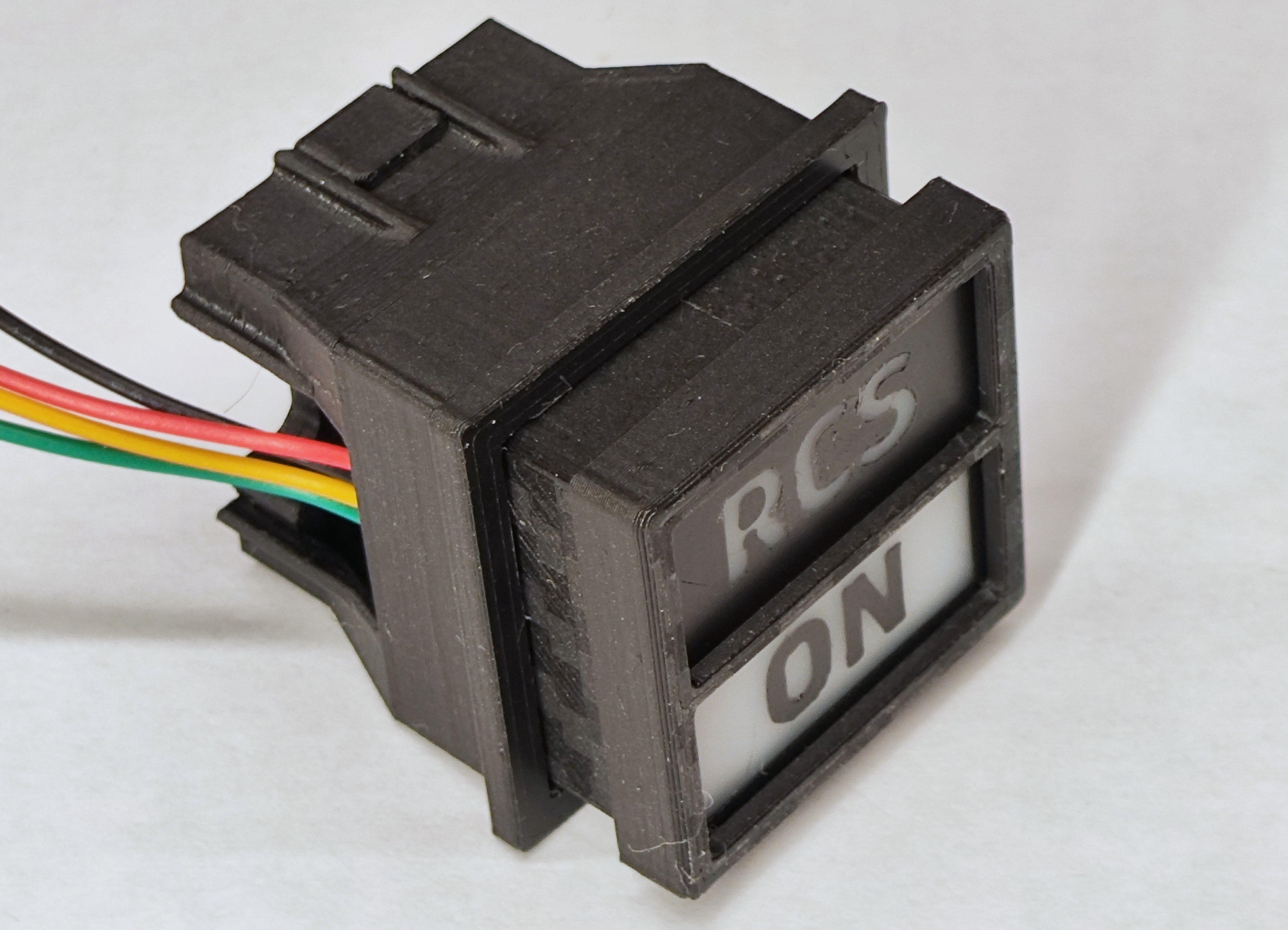
I did some reasearch and found out that this type of illluminated button seems to be called a “Korry switche” after the manufacturer Korry who makes them for commercial airliners. I decided to create a design similar to their 433 series 1-inch switchlight they have a datasheet that gave me a starting point for sizing.
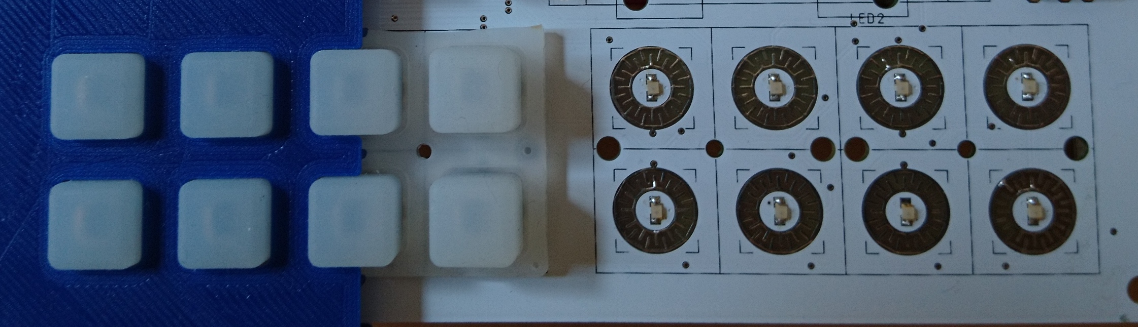
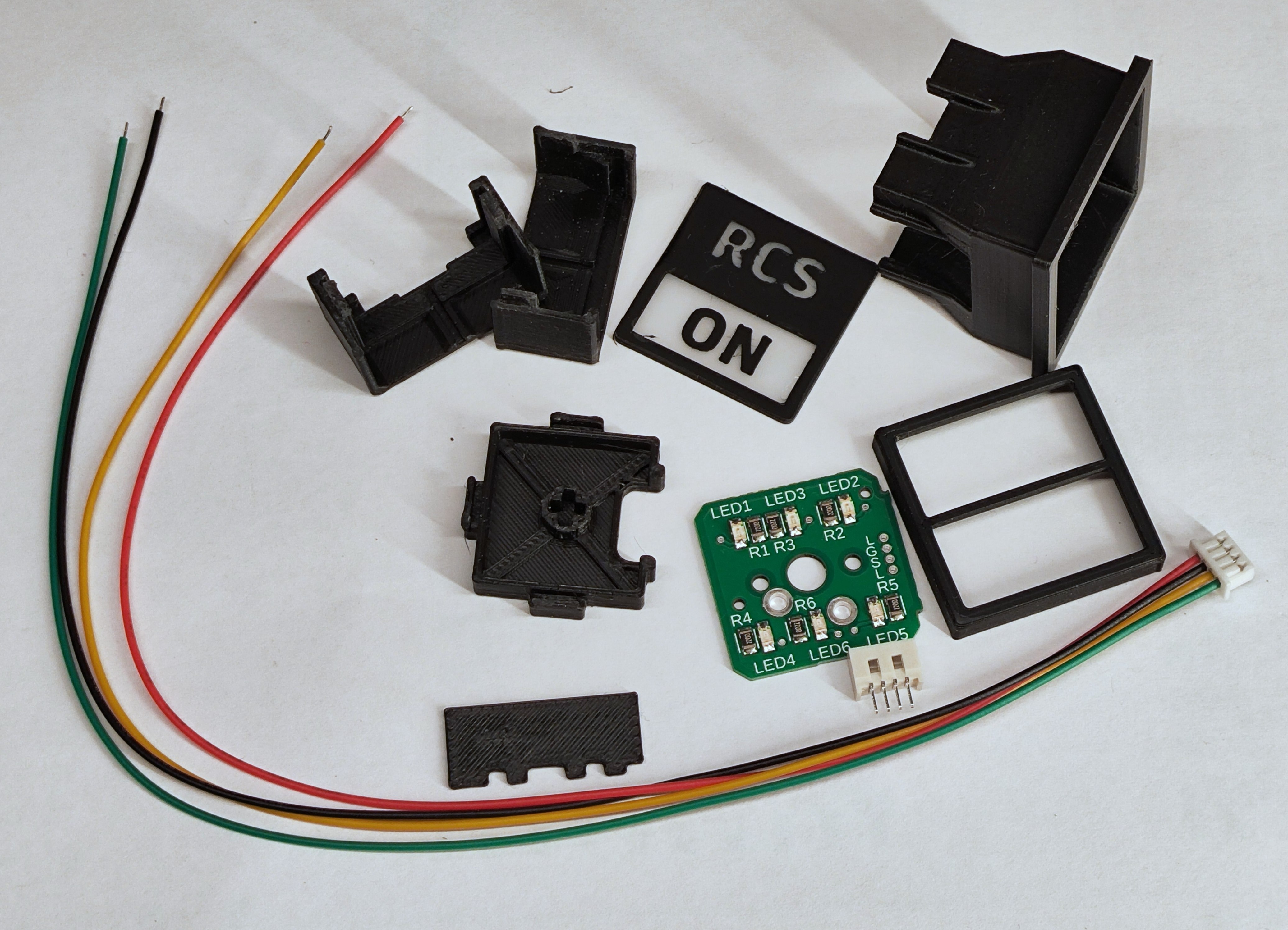
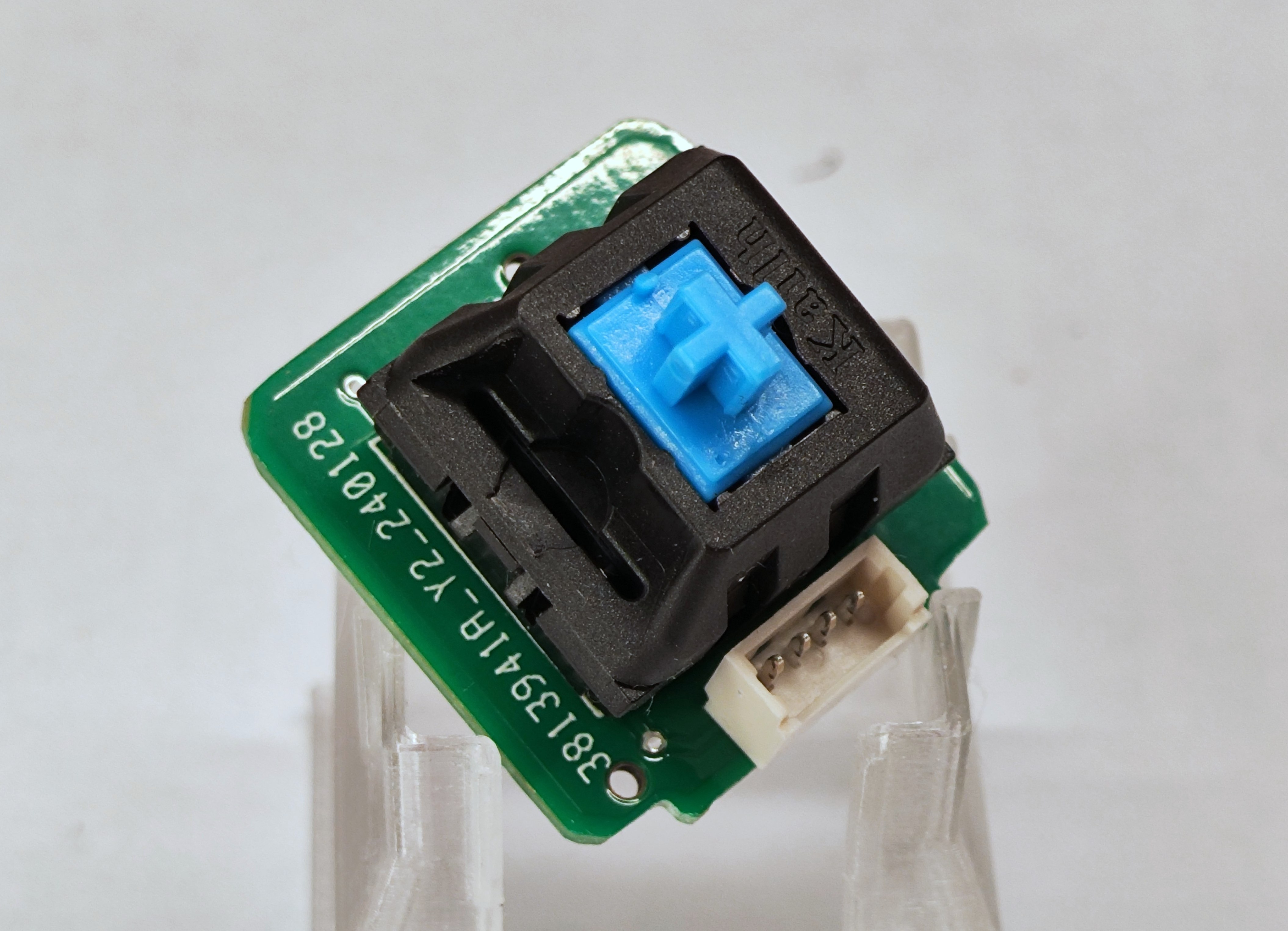
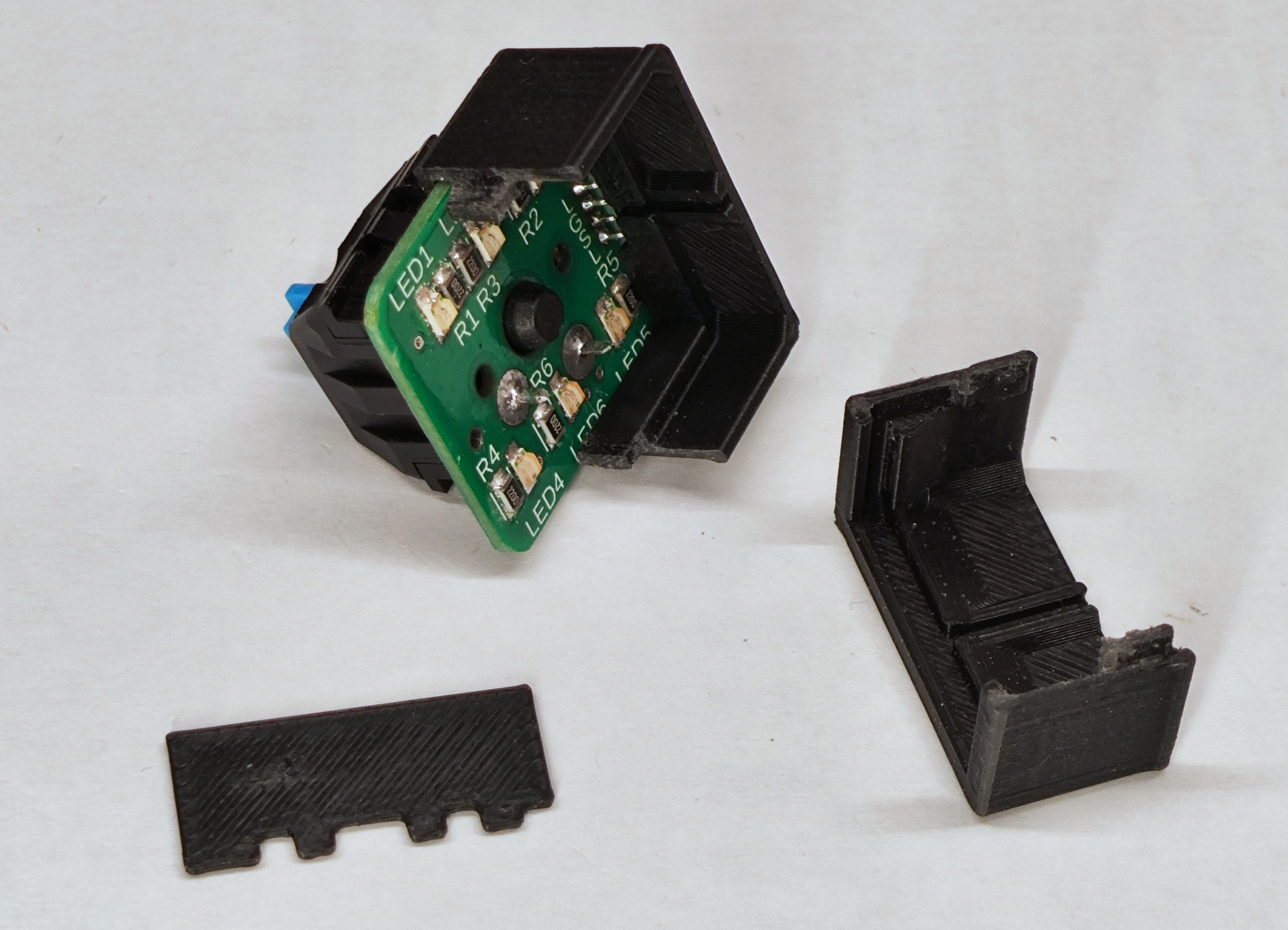
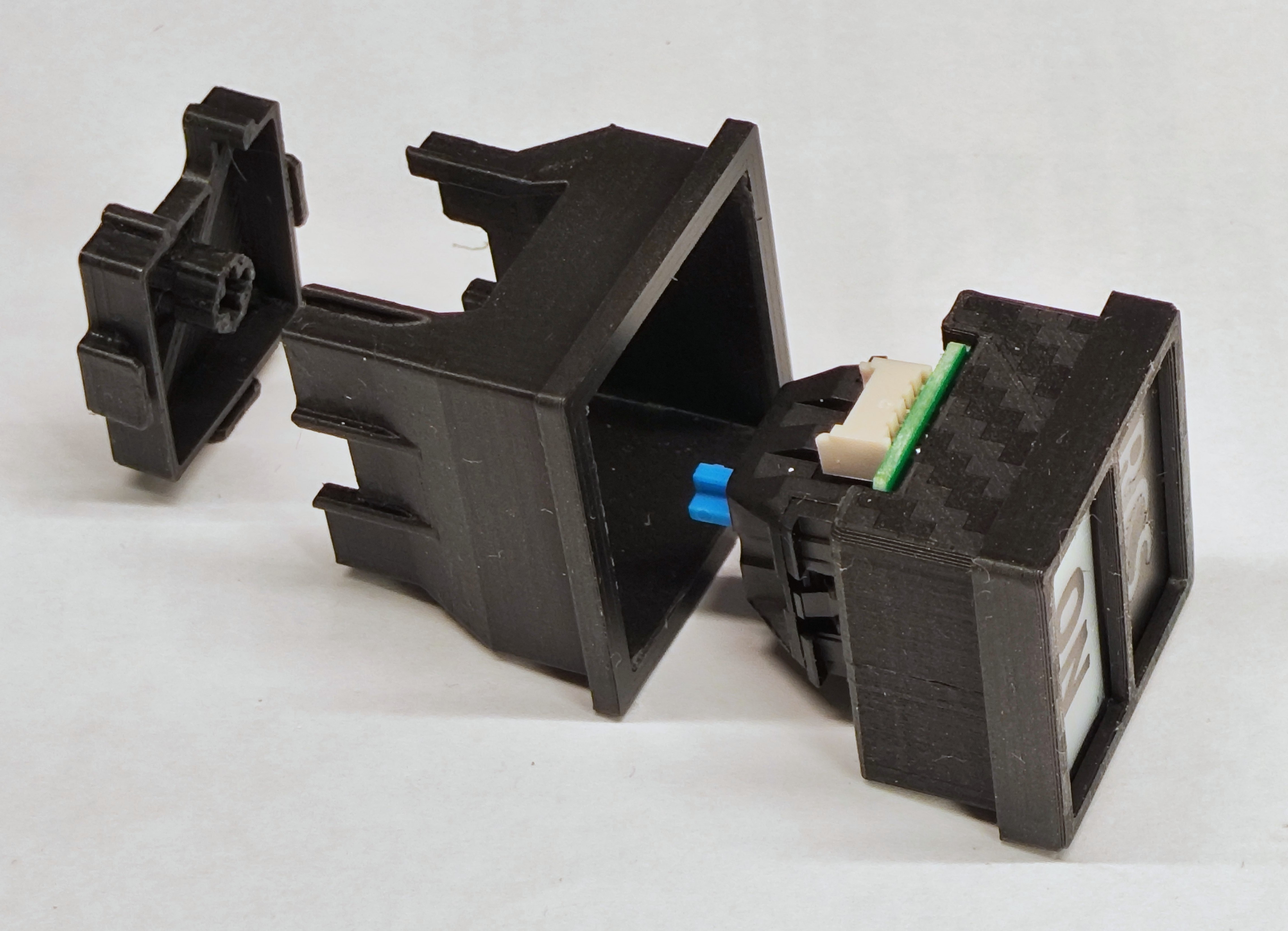
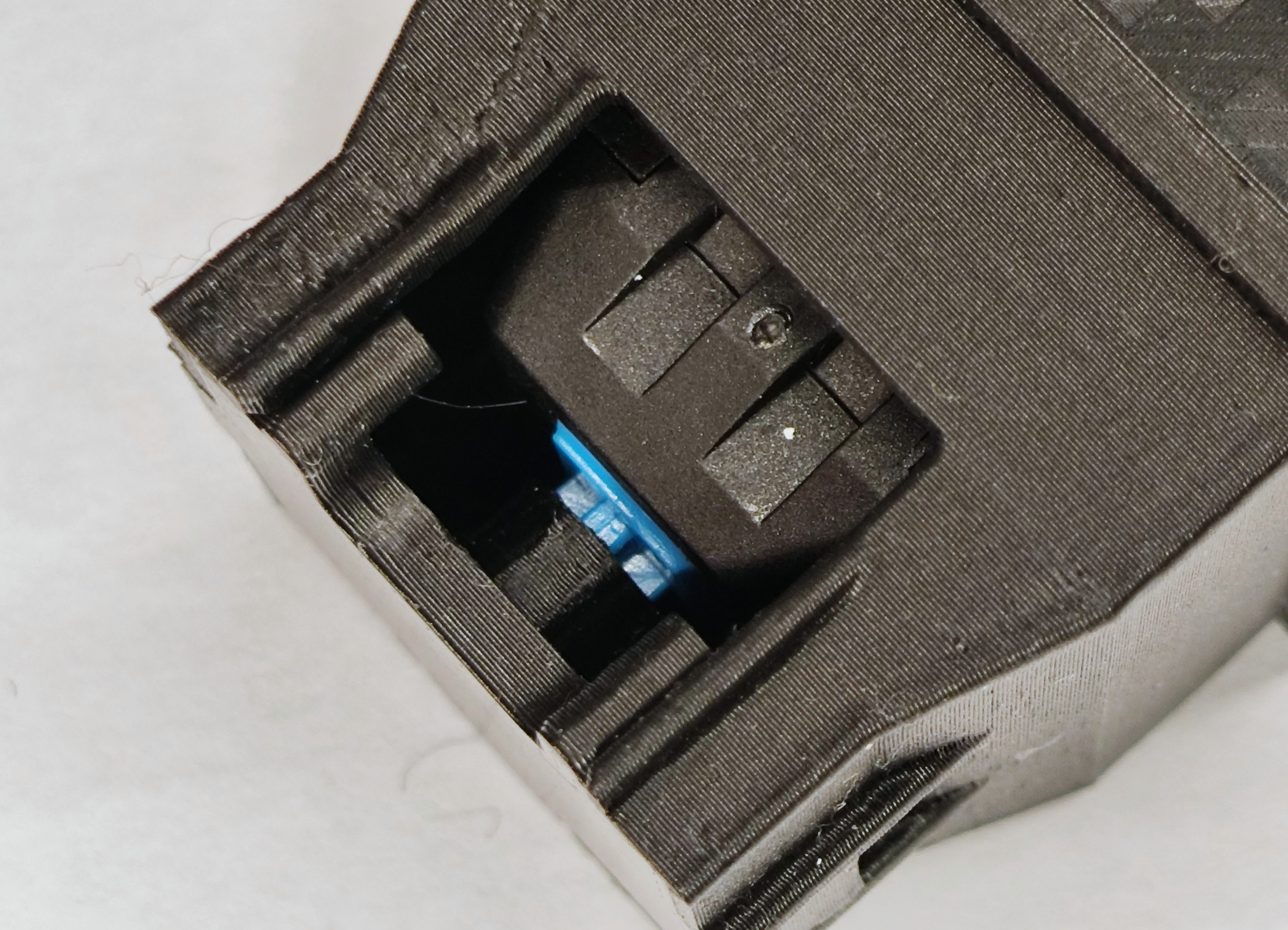
I wanted my switch to be simple to assemble from mostly 3d printed parts. I also wanted it to be self contained so I decided to design a PCB to hold the button and LEDs. I also thought it might be nice to use proper mechanical keyswitches for the action. They have a decent amount of travel – around 3.5mm – and give a satisfying click. I just happened to have a cherry keyswitch in my parts box so I could get started with that whilst also ordering some new switches (again from Aliexpress)
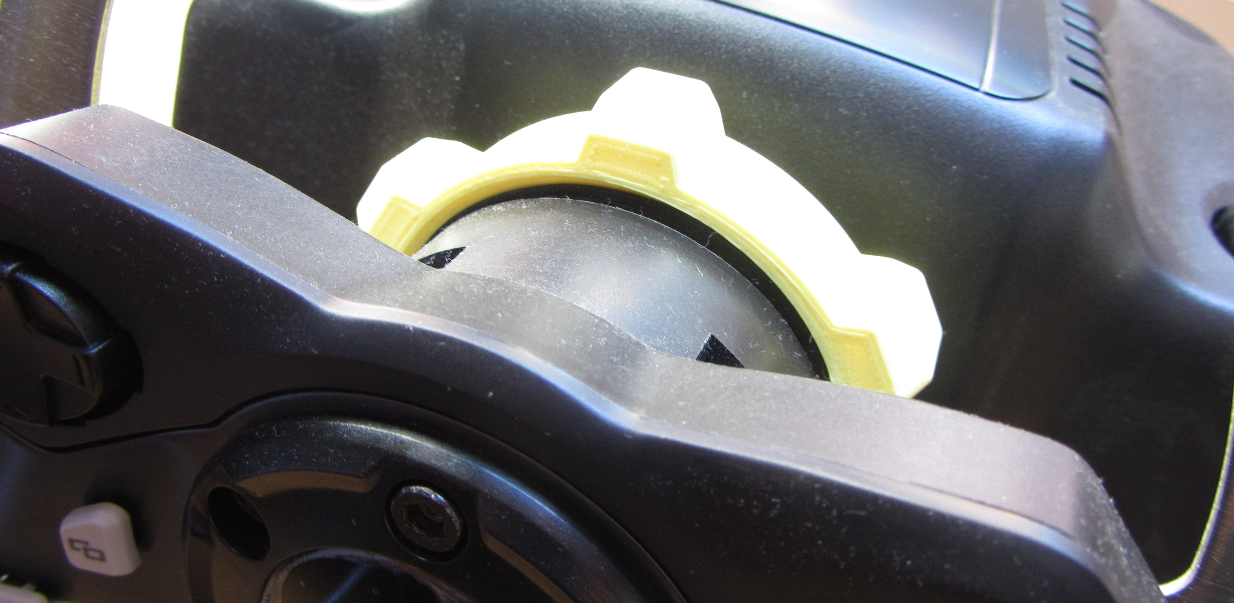
- The switch is designed to be panel mounted in a 24mm square hole.
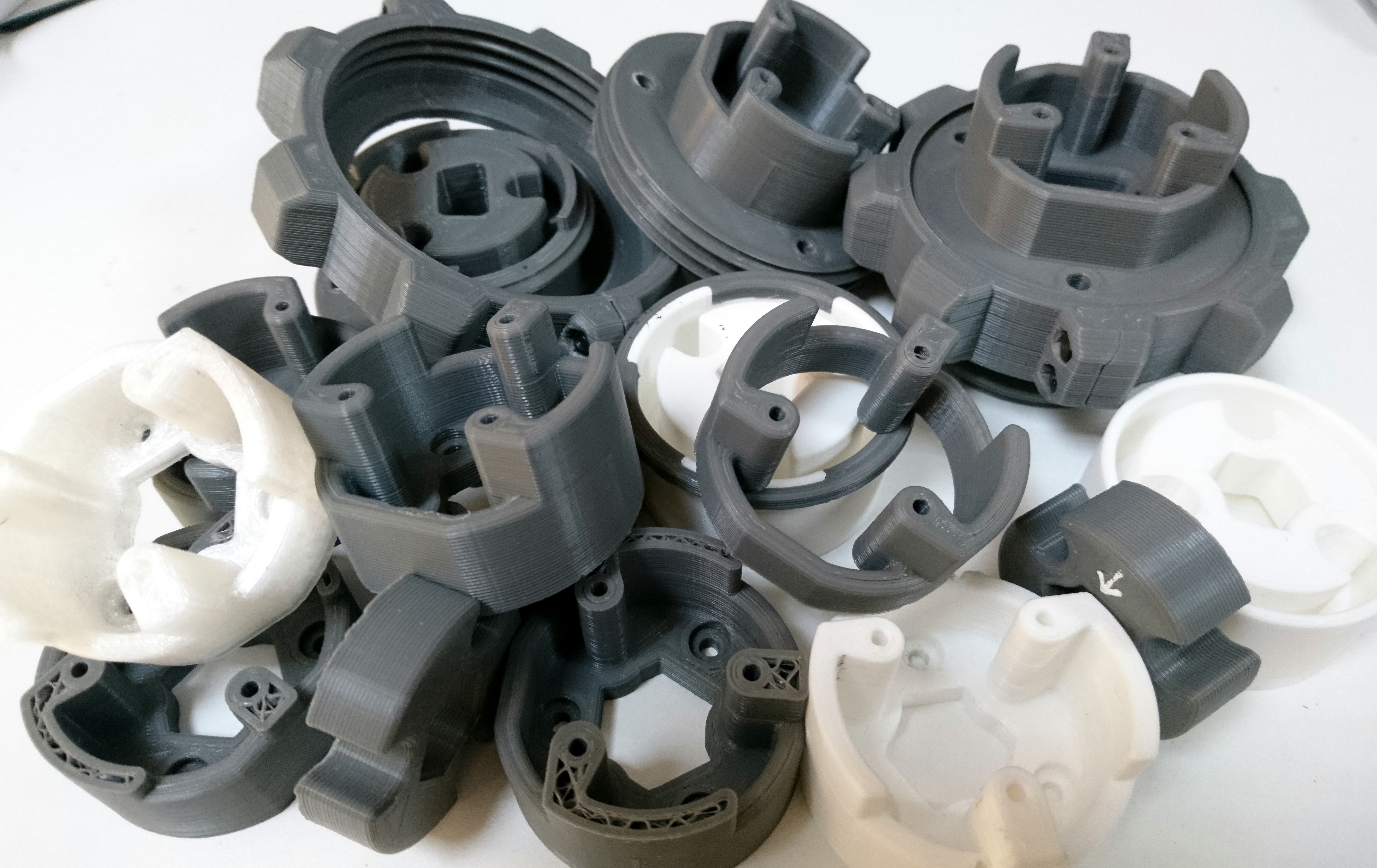
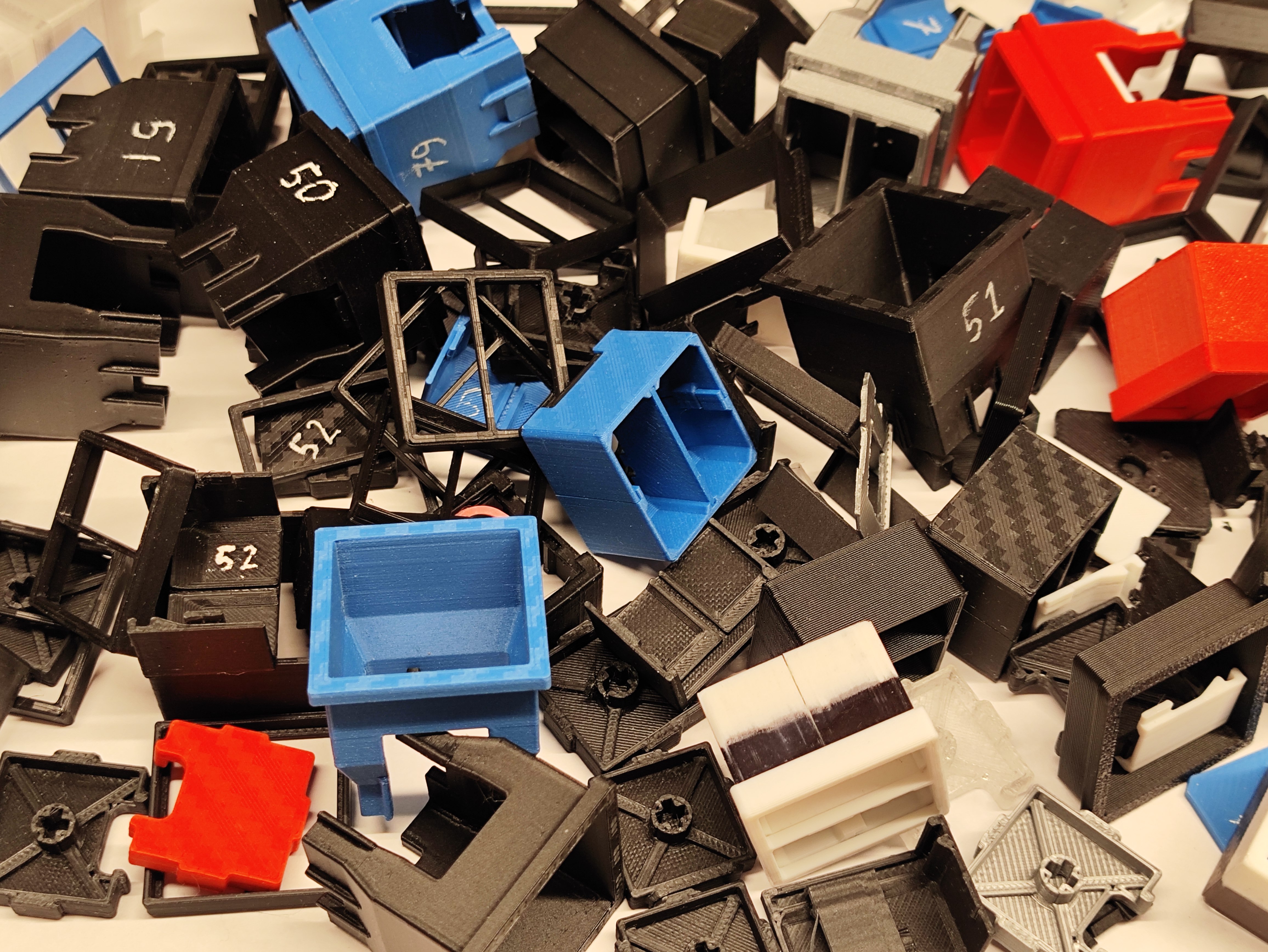
- All parts are printed in PLA or PETG using a 0.4mm nozzle. No supports needed.
- 1 entire set of parts prints in approx 50 minutes on Bambu A1
- The body of the switch projects 24mm behind the panel face.
- The front face projects 8mm out from the panel face.
- The button has a travel of approx 3.5mm (with a nice click if you choose a clicky switch).
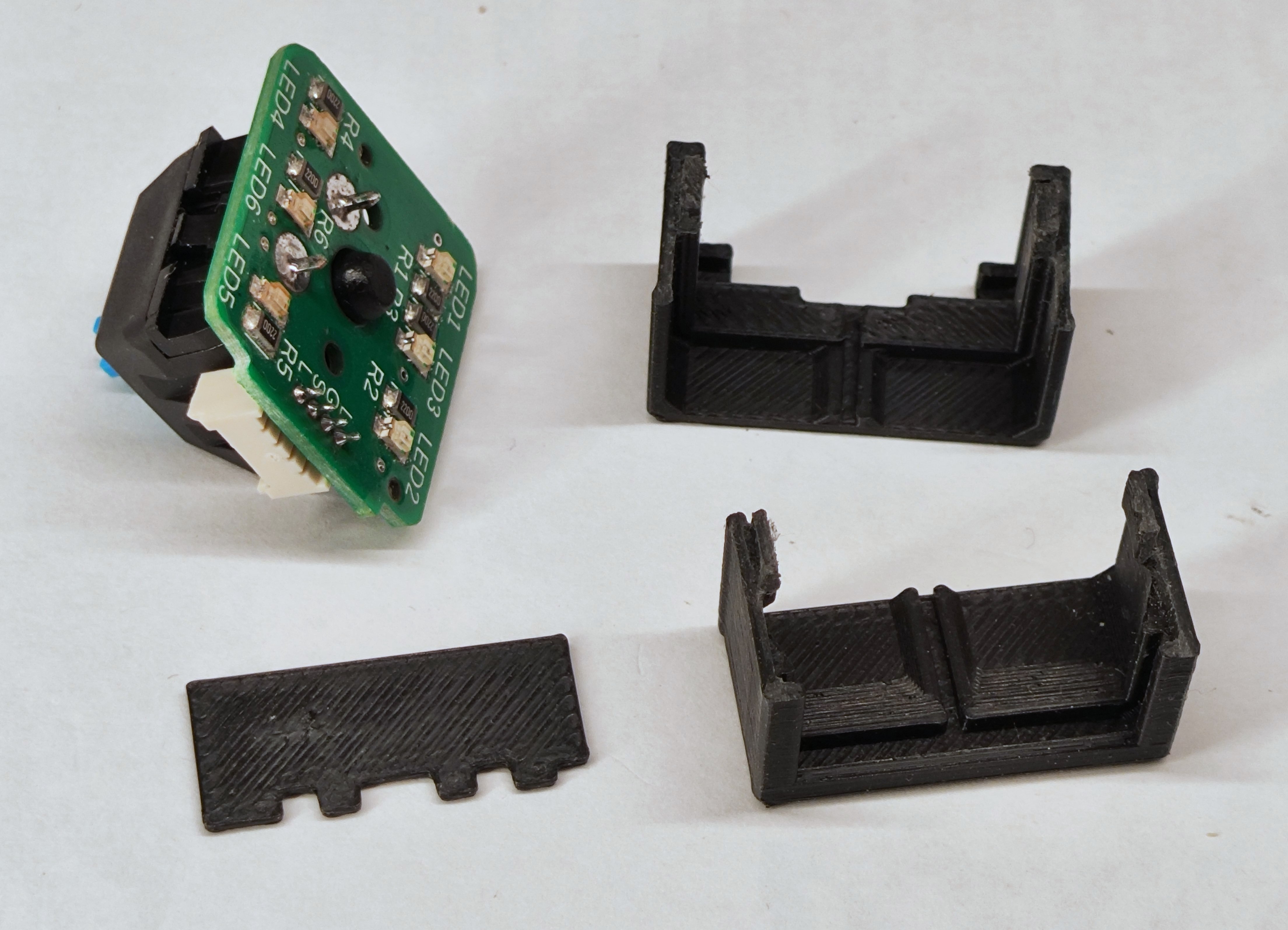
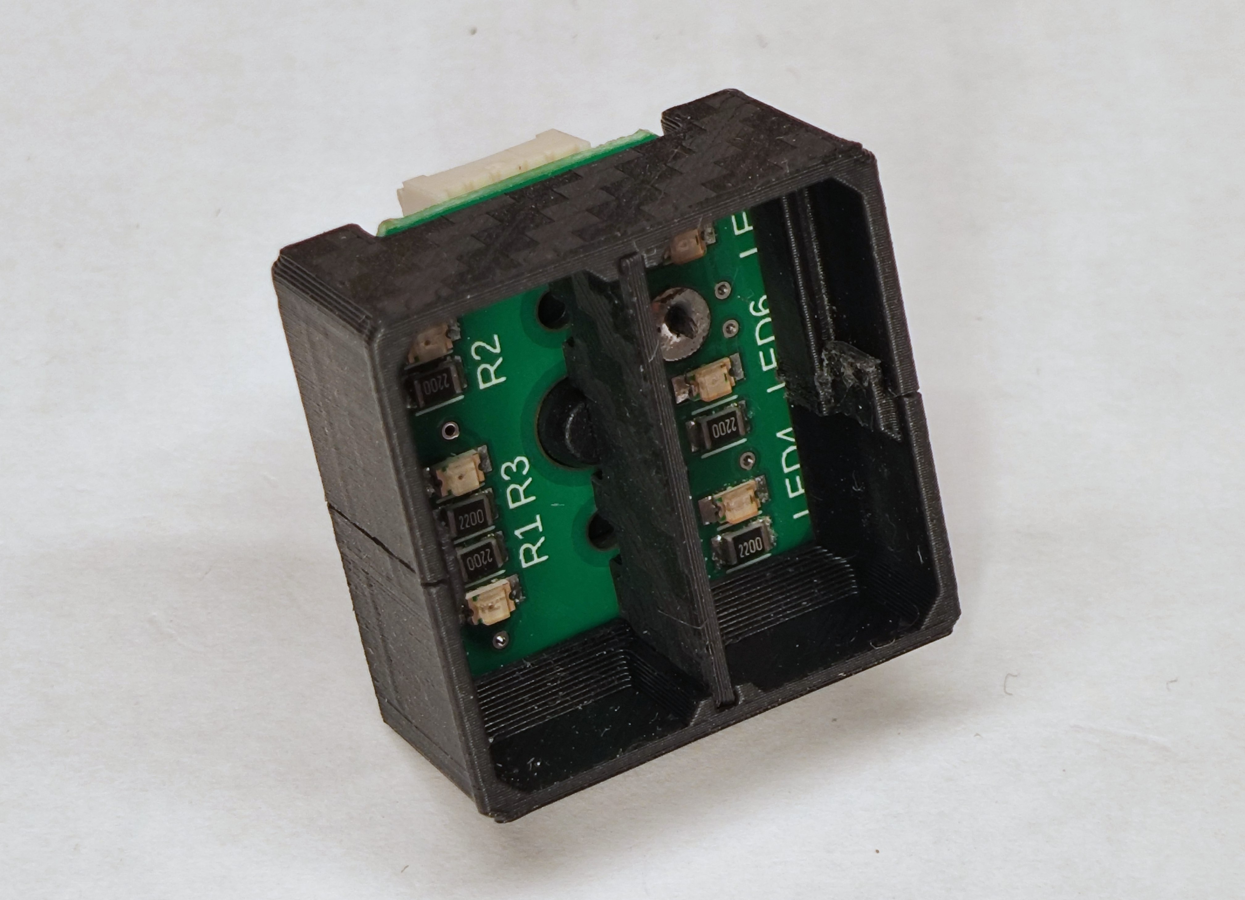
- The inner shell (the part that moves) is designed to printed such that the layer lines are perpendicular to those of the outer shell to reduce binding.
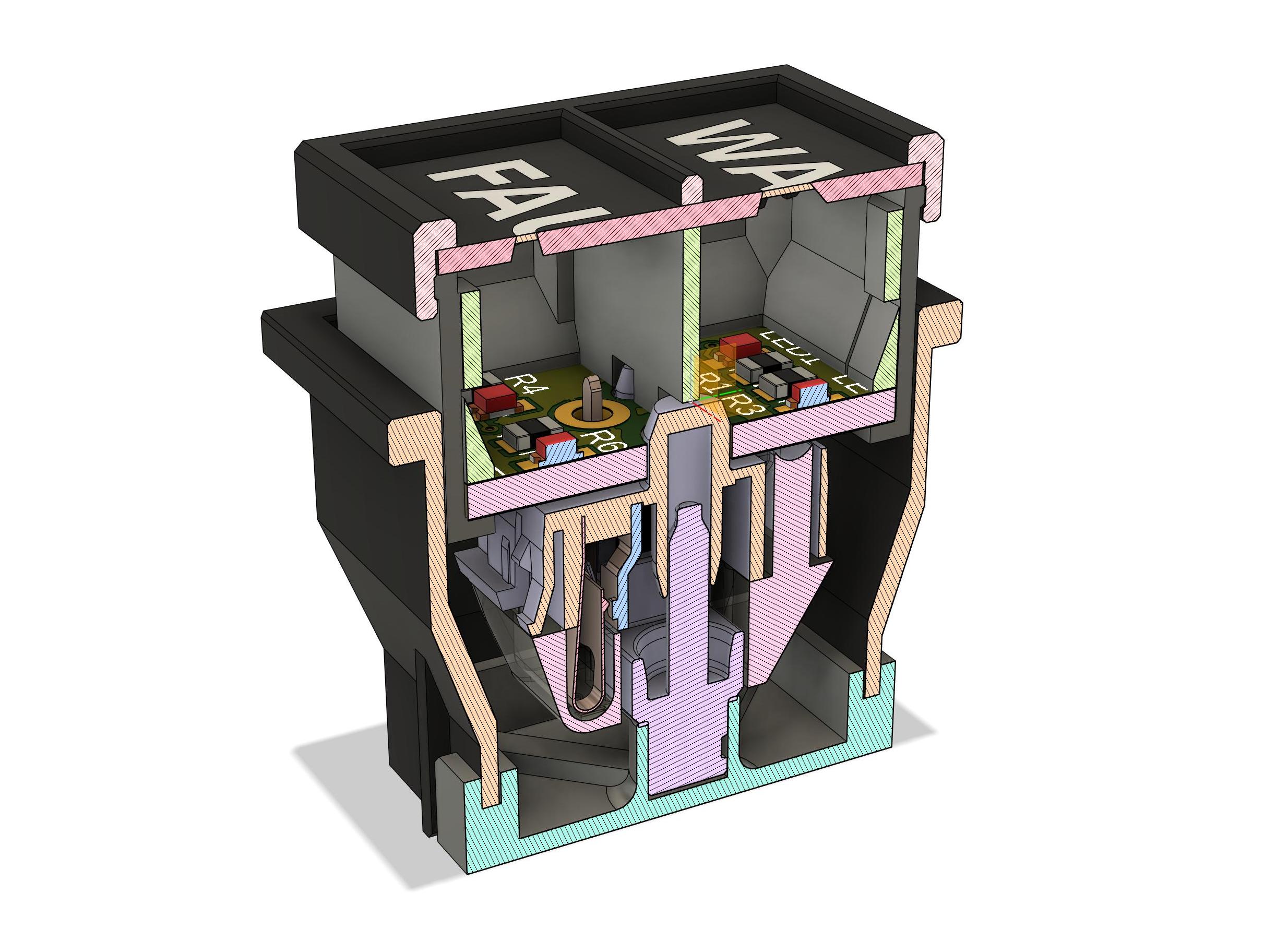
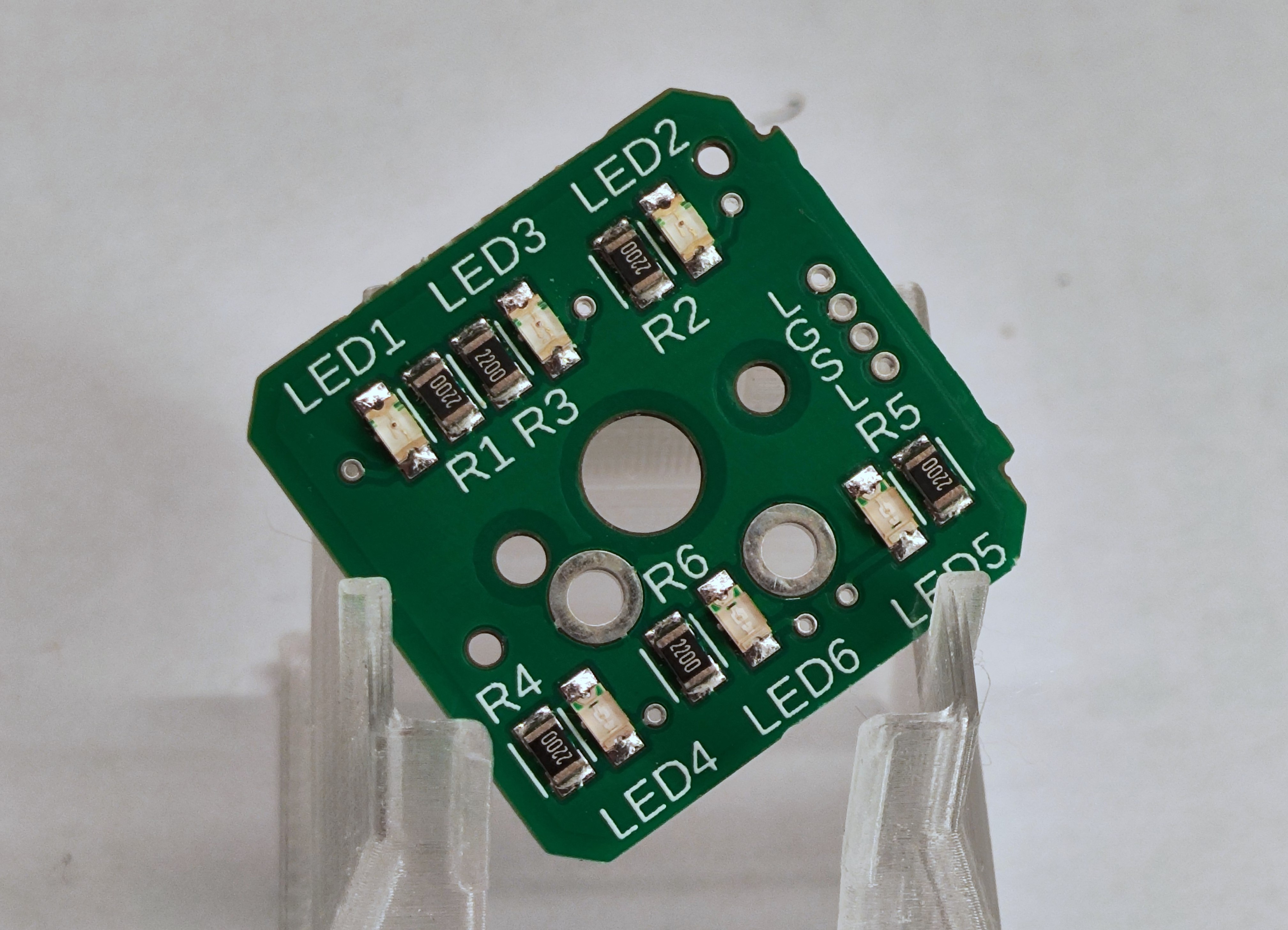
- The PCB carries 6 LEDs in two strings of 3. Each string can be independantly switched.
- The mechanical switch is also mounted to the PCB (in reverse if you like) to simplify electrical connection.
- A 4 pin 1.25mm JST connector carries GND, Switch, Led 1 Anode. LED 2 anode.
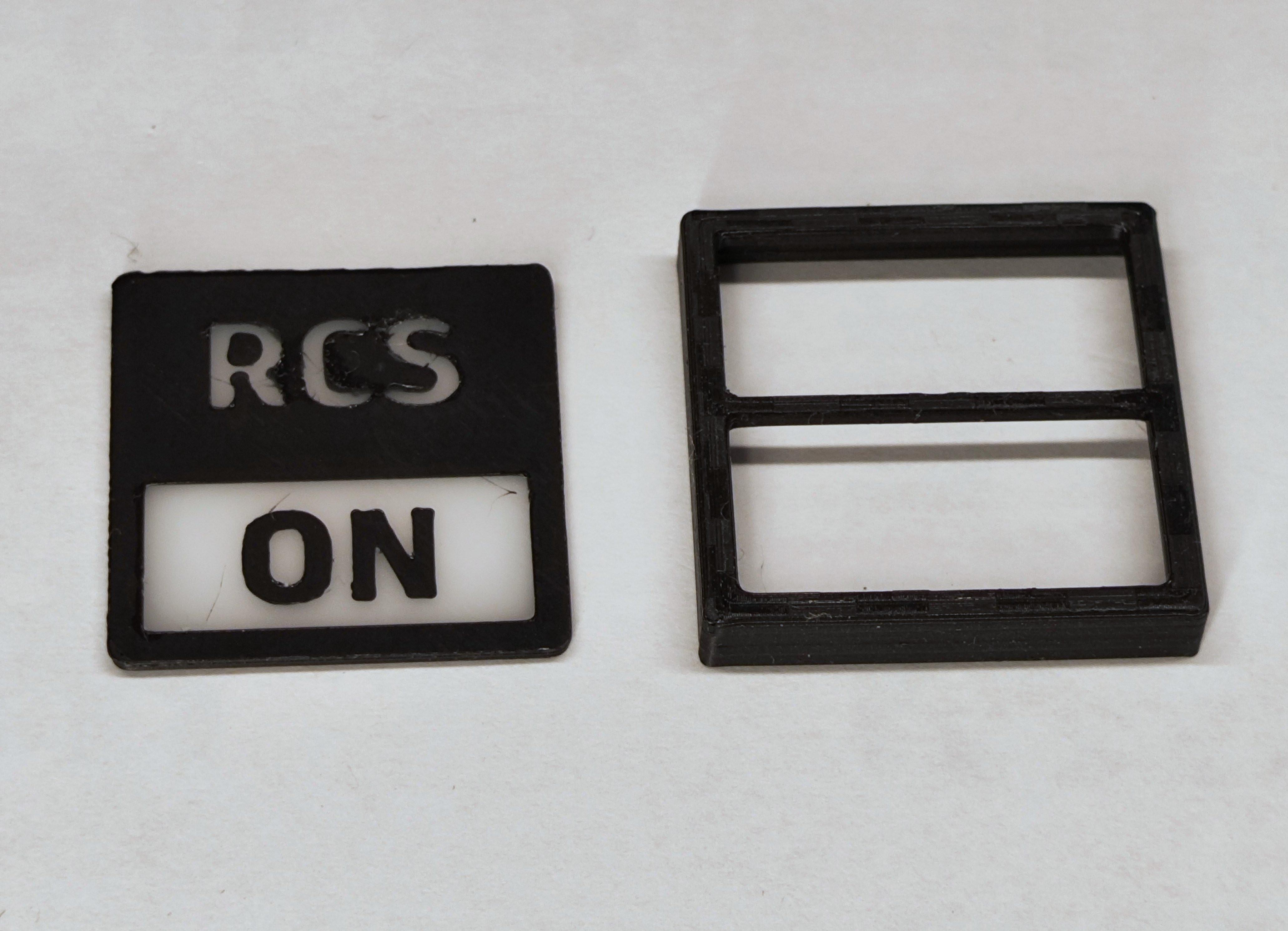
Face tile developments
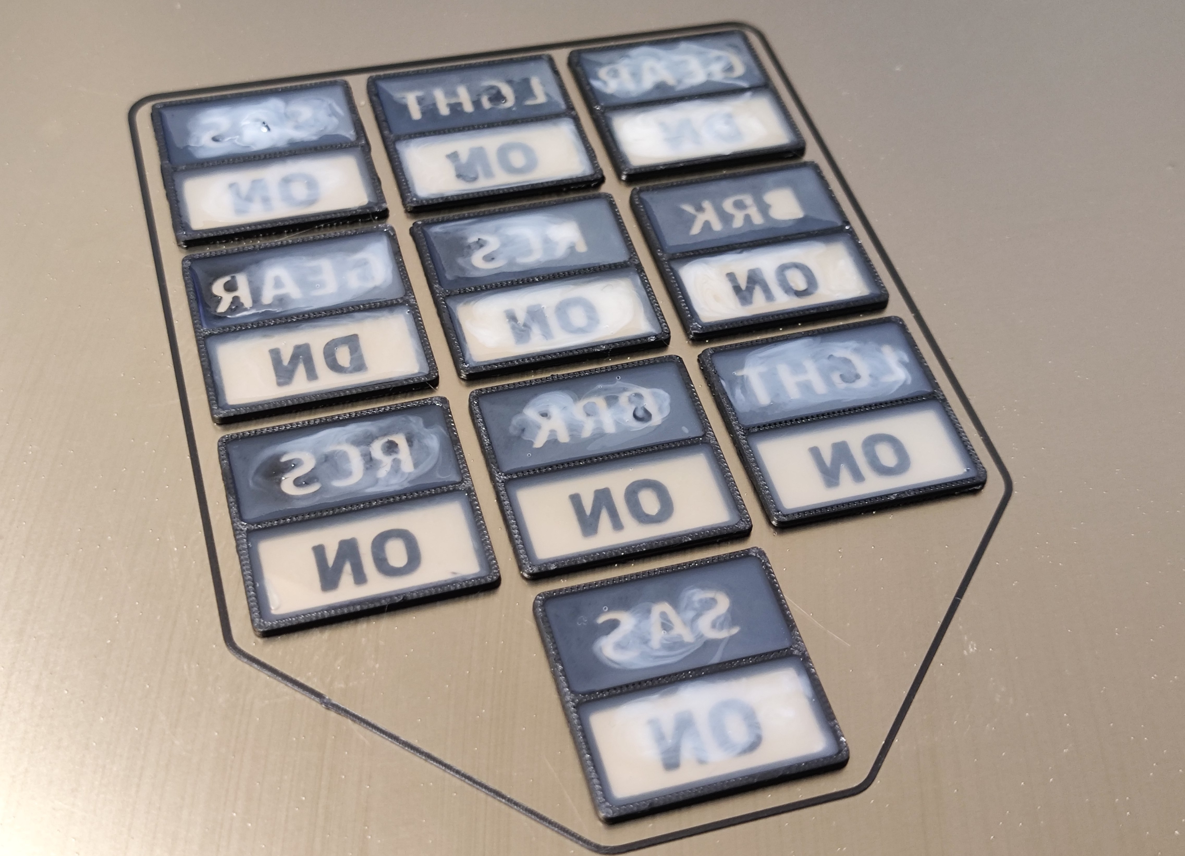
Alixepress delivered a whole bunch of different UV-curing resins in various colours plus some pigments that are supposed to work with resin (but maybe not with UV-curing resins)
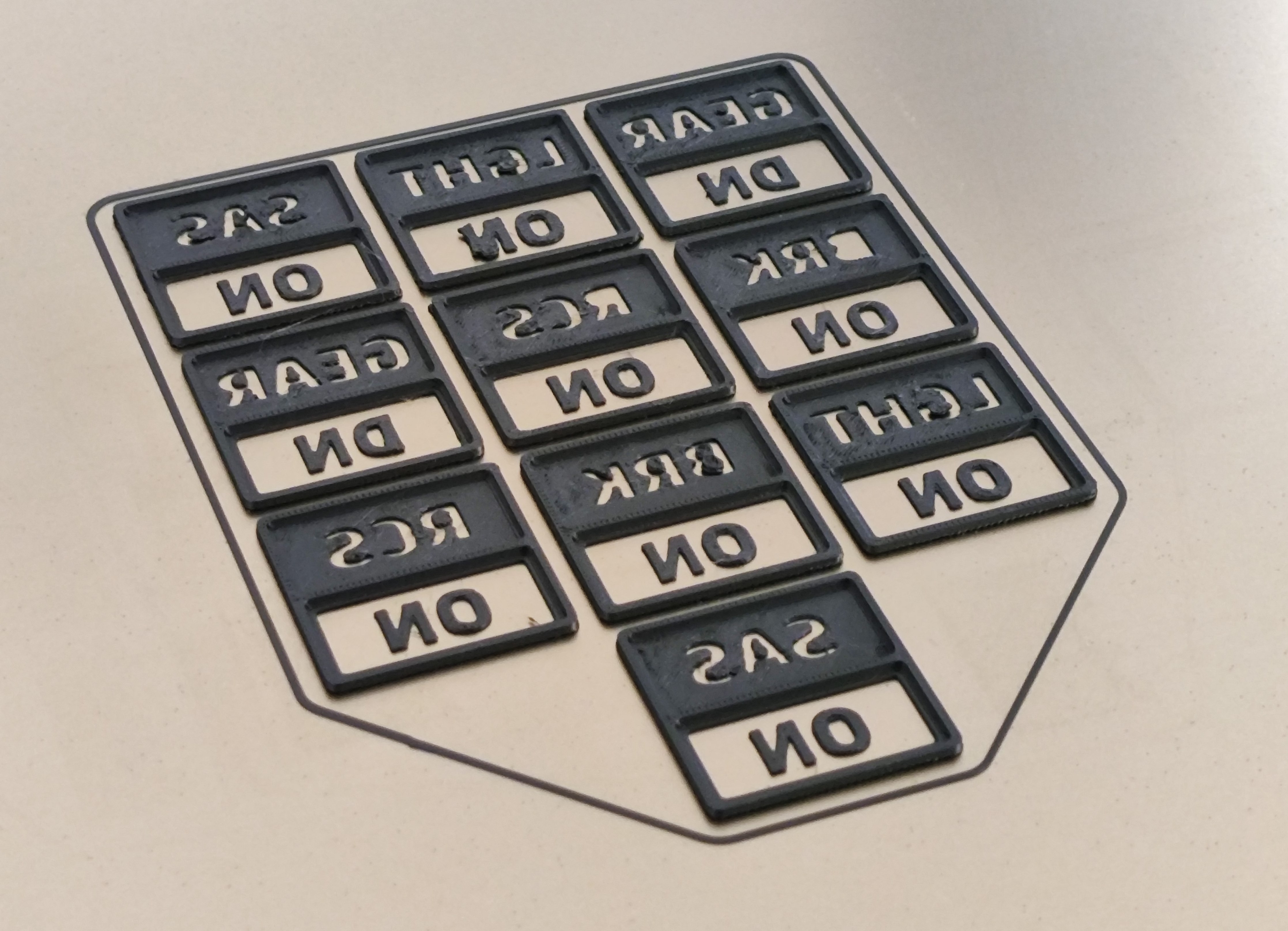
I didn’t want to remove the parts from the build-plate before filling them with resin, that would be far too likely to end up in a mess. I was hoping that the printed plastic’s bond to the build-plate would be enough to keep the resin contained. Also I thought that the heat left from after the printing would help the resin to flow more easily. But I wasn’t sure if the resin would bond to the build-plate. I did some tests and it seemed ok, but to play it safe I initially printed on top of a layer of polyimide tape (Kapton) which I could always peel off the build-plate.
Here are some early samples using translucent coloured resins the PLA prints came out well enough for this test but I think my filament needs drying out or something as they are not as clean as my earlier tests.
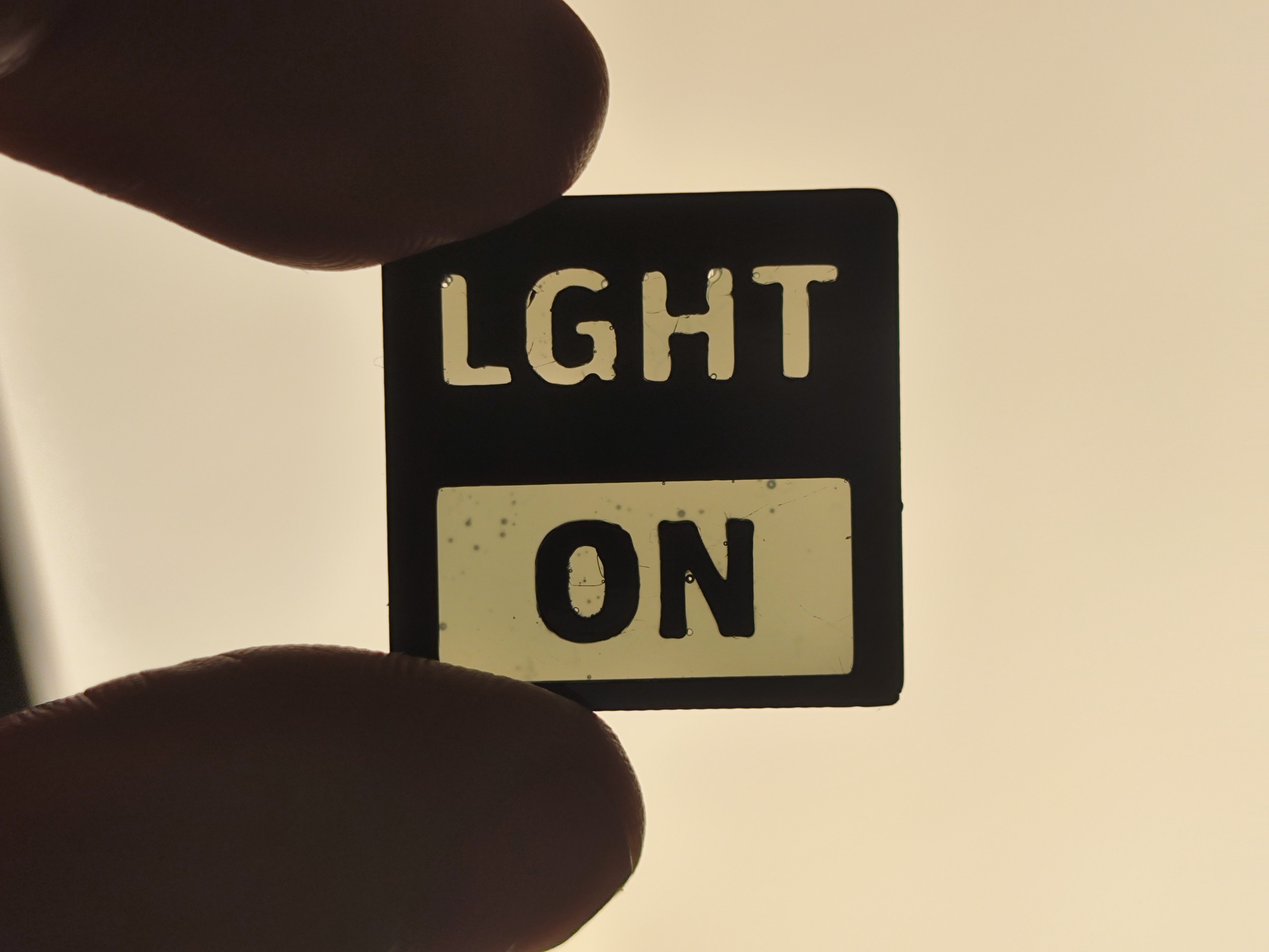

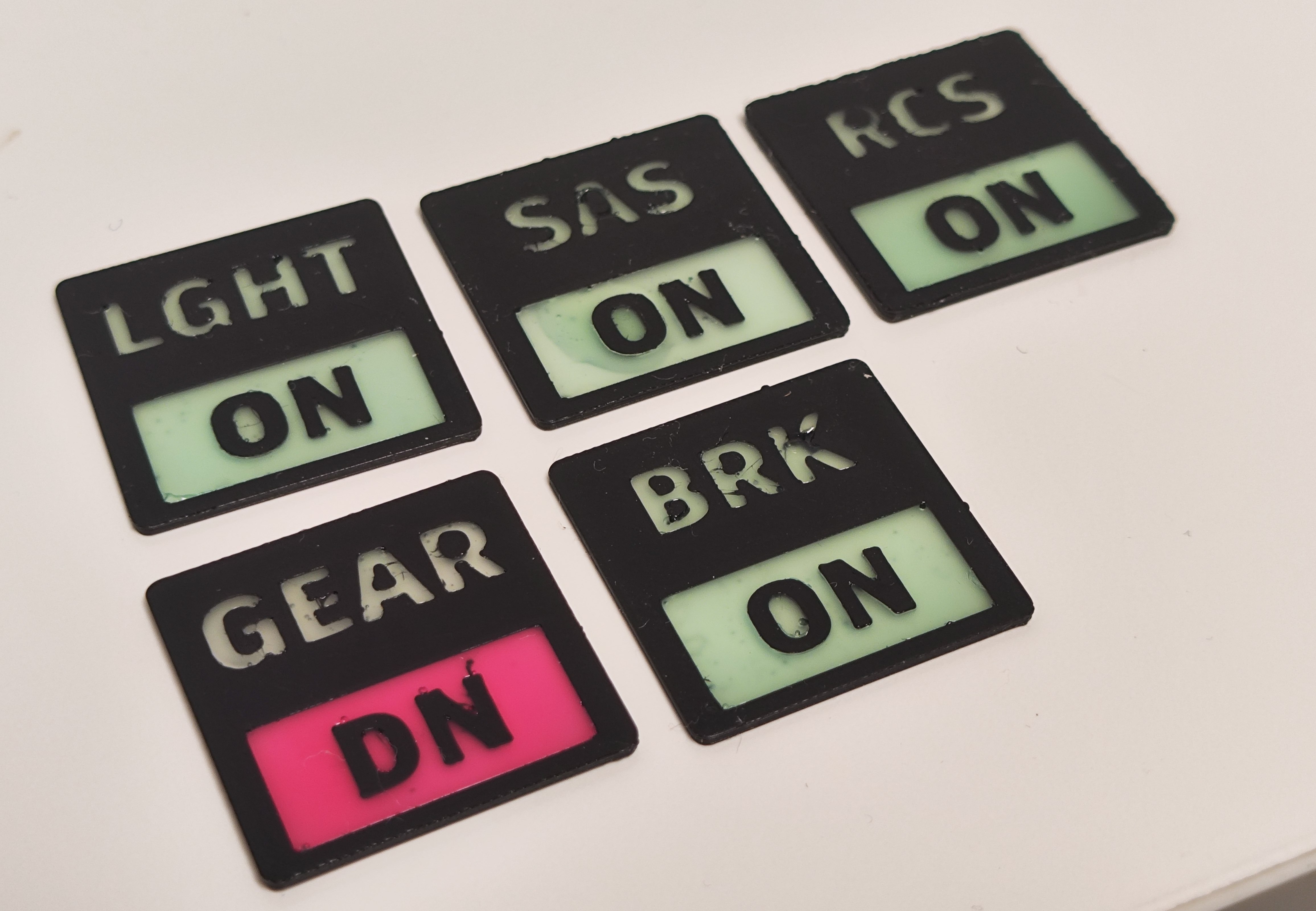
In the end it turns out that the resin doesn’t bond at all to PEI build plates. It just flicks off nice and easy once it’s cured so there was no need to the extra hassle with the tape. Later tiles were printed directly onto a smooth PEI plate
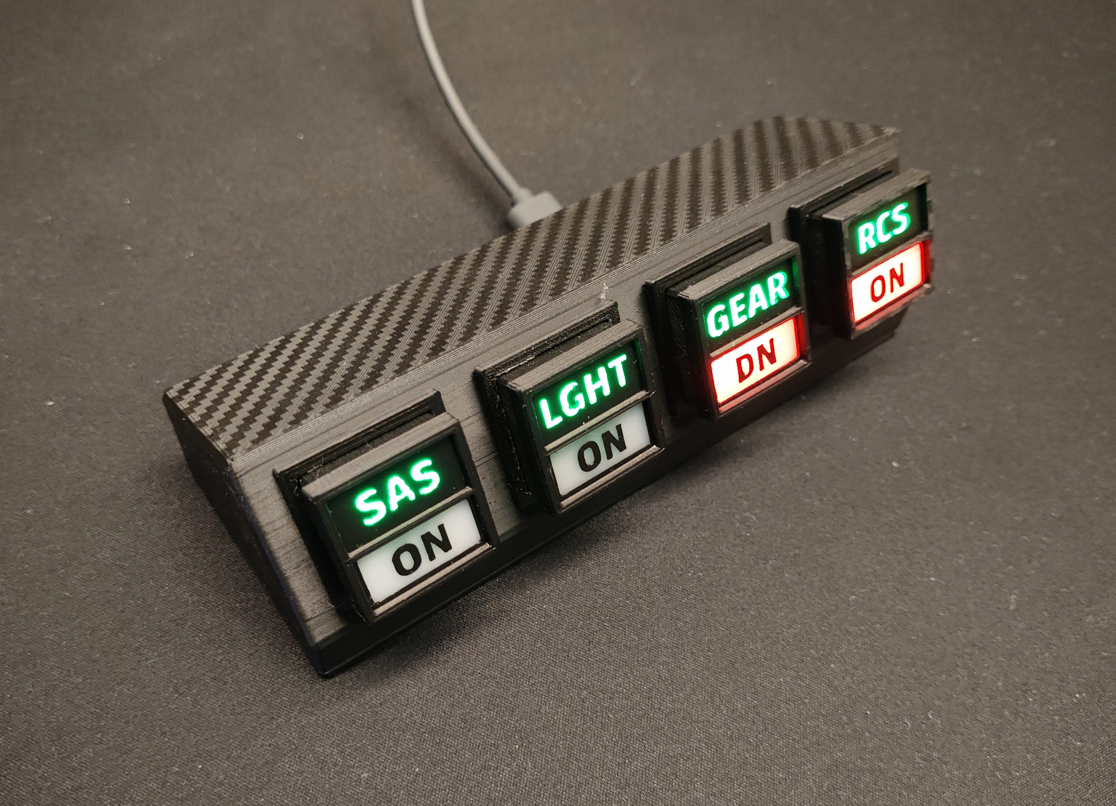
Mini Kerbal control panel
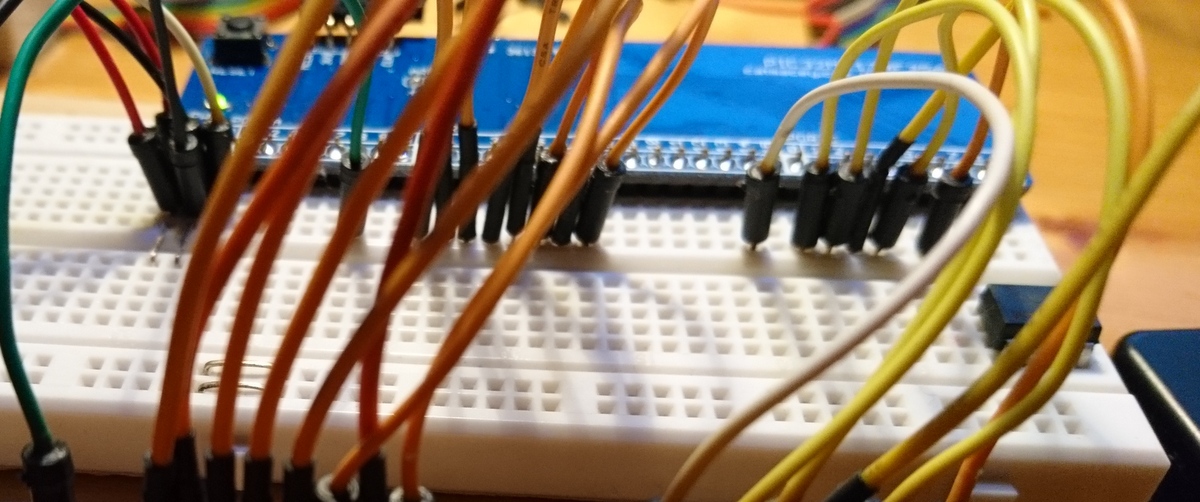
This is starting to wander off into the woods now. I wanted to see the buttons actually doing something so I designed and printed a simple box to house 4 buttons for use as a control panel. Gear, SAS, RCS, Lights… Oh and Brakes too. I Should have made it 5. Nevermind.
I grabbed a Waveshare RP2040-Zero board that I had hanging around and used the KSP Serial IO plugin I had used before to build this simple controller.

If you are at all interested the code is up here GitHub Catmacey/KerbalButtons.
Here’s a quick video of it in action.
That’s it. Time well spent I think…?