I found some time this weekend to start assembly of my Chipstomp’s.
The digital side of the Chipstomp is assembled and up and running
I started with the digital side of things. The first task being to get the PIC and it’s supporting circuitry up and running and confirm that all was ok by attempting to talk to it with my PicKit 3.

Pretty much the bare minimum components needed to check that the PIC can be programmed
After assembly and half an hour of head scratching I found my first mistake. Some how along the way I connected the ICSP clock line to pin 2 rather than pin 5 of the PIC. Luckily this wasn’t to hard to fix with a knife and a small bodge-wire.

A small bodge-wire to fix a mix up in the ICSP connections.
Once that was done the Pickit 3 detected the PIC ok and I could program and (and verify) the Chipkit DP32 bootloader.
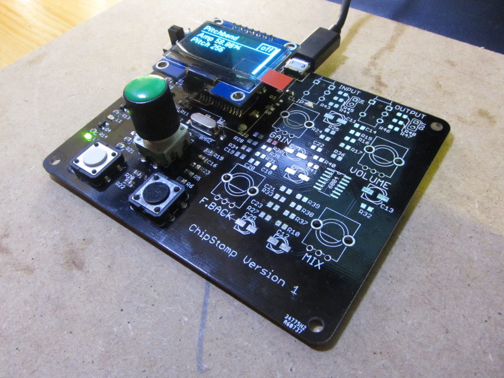
Next was to install the UI elements (Buttons, encoder and LEDs) and the tiny USB micro connector. Once done I got a nice blinking LED indicating that the bootloader was waiting for new code and plugging the USB cable in gave me a new STK500 device in Windows device manager . All good so far!
So I started up MPIDE (Chipkit’s Arduino IDE), selected the COM port and managed to upload a program to the board right away. But afterwards things were not quite right, as after uploading the board appeared to be stuck in boot-load mode never running the main application.
The reason soon became apparent. The Chipkit DP32 has it’s button inputs setup as normally low with a pull-down resistor. Pressing the button brings the input high. I had designed my circuit the other way round with the input normally pulled high, with the input being pulled low when the button was pressed.
I remember making this decision whilst drawing up the schematic – it just seems to make more sense to me to have buttons pull low – but I didn’t think about how that would effect the bootloader.
 My inputs are all pulled high |
 The original Chipkit DP32 inputs are pulled low. |
When the PIC is reset the Chipkit bootloader looks at the state of the “prog” button – the black one in my case – if it’s pressed (high) then it enters boot-load mode, if not pressed (low) then it jumps into the main application. So the problem here was that in my case with my buttons normally high the bootloader was always being activated and sat there waiting for new code every reset. I could confirm this by booting with the prog button pressed (low) which skipped boot-load and ran the main application.
So what to I do? Modify the circuit? Or modify the bootloader? Well I couldn’t be bothered with messing about with the circuit again so I opted to alter the bootloader.
The Chipkit bootloader code is open source and available on GitHub. The project code is well documented and thankfully the change I needed to make was already built in as a simple config option. All I needed to do was create a new board definition section in BoardConfig.h – copying the config for the DP32 – and change a single line to tell the bootloader the the prog button would be active low rather than high.
#define BntOn High
#define BntOn Low
Easy, now all I needed to do was compile it and upload it to the PIC.
Unfortunately it wasn’t quite as simple as that. In order to build the bootloader project without further modifications it must be compiled with optimisation level “s” (optimise for smallest code size) and the “generate 16 bit code” (MIPS16) option set. These two options drastically reduce the size of the final code, but unfortunately neither of these two options are available in the free version of the XC32 compiler.
I believe that it’s possible to build the project without these two options, but firstly you need to be happy with the bootloader taking up much more space and secondly you need to alter the project linker script to take this new larger size into account.
Luckily for me there is another option… Microchip offer a free 60 days trial of the pro version of the XC32 compiler by signing up for it on the Microchip website. With this installed I could compile my modified bootloader without having to modify any thing else. I’m just glad I hadn’t already used the 60 day trial as I would have been stuck without it.
With the new modified bootloader compiled and loaded onto the PIC32 things started working as expected. On a normal reset the device would start the main application. If the PROG button was held down during reset the device enters bootload mode. Perfect! I could finally start to get things up and running.
Plugging in the OLED screen brought up the display as expected and pressing the buttons had some effect, but not quite what I was expecting and the rotary encoder didn’t seem to be doing anything at all.
I have a Digilent Analog discovery multi-function scope/logic analyser thingy. It’s a really handy tool being both a dual channel scope and a 16 channel logic analyser all in one (as well as many other things). Connecting this up using both analogue and digital channels showed that the rotary encoder appeared to be working fine and that the signals were as expected and making it all the way to the PIC. But a bit of a closer look at the signal levels using the scope showed that the voltage of the low part of the signal was not very low at all, dropping to only around 1 volt. The problem again is that I didn’t really think things through here, I copied the Stompshield side of the circuit more or less as is, but decided to include 10K pull-up resistors on the encoder inputs in my version. Not sure why really as on the prototype I just used the PIC’s built in weak pull-ups. Anyway, in retrospect it’s obvious, a 10K pull up resistor combined with the 3.9K I have inline forms a voltage divider when the encoder pulls the its signal low meaning that the input will never be pulled to zero, only near it. The ratio is such that the voltage is around 1 volt. The formula is (3.9K / (10K + 3.9K)) * 3.3V = 0.925V which taking into account resistor tolerance and such like is pretty much what I was seeing. This is too high a voltage for the PIC to “see” as being a logic low.
The PIC32 has two thresholds for digital logic inputs that determine if the PIC considers the input High or Low.
Input Low Voltage (VIL) is the level below which an input is considered logic low (0).
Input High Voltage (VIH) is the level above which an input is considered logic high (1).
The exact levels depend a little on the particular pin and also on the supply voltage but in my case for the pins in question at 3.3V, VIH is 0.65 VDD (2.145V) and VIL is 0.2 VDD (0.66V).
So it’s clear that 1V was neither here nor there and not surprizing that the PIC didn’t react to the encoder inputs. The simple solution here is just to remove the pull-up resistors and rely on the PIC’s built in weak-pull up feature as I had done in the prototype… With that done I am getting the input I expect.
Other than mistakes, this version of the Chipstomp differs in some deliberate ways to the prototype. As noted above the inputs are pulled high not low and I’ve also added one extra button to the board making three in total – two 12mm tactile buttons plus the “push” button built in to the rotary encoder.
Another small difference is that rotary encoder is wired in such a way as the direction is reversed. Turning it clockwise currently decreases input values rather than increasing them as you might expect. The reason for this is that it happened to make PCB routing easier if I switched the encoders A and B signals.
A few small changes to the software and a fresh upload and these are resolved and brings me to the end of the digital side of things. The next stage is to assemble the analogue side of the circuit and do some testing. Then assuming all is well I can continue with the development of the software with a nice stable base to work from. Of course the software’s not finished. My core four effects are pretty much complete, but there are new ideas to try out and I’ve yet to decide exactly how I’m going to use the extra button. But this brings now to the me up the the same point as I was with the prototype.
Again assuming all is well with the analogue side I’ll also need to start assembling a second board to send to my brother.
That’s all for now.

Pingback: Chipstomp assembly – Digital side | PCB공유.COM