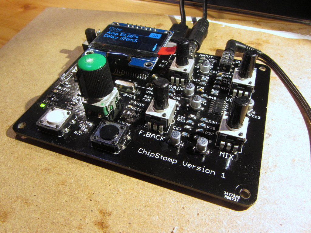
Fully assembled and working Chipstomp
It’s done. I’ve assembled the analogue side of the Chipstomp and finally have a fully working device. There were no errors to fix this time which was a nice surprise. Just lots of fiddly 0805 surface mount components to place.
I’ve made a quick video of the project to demonstrate what it can do.

Pingback: Chipstomp assembly – Analogue side – RLabs
Hi,
Nice project, original found the page as trying to access the quality of DirtyPCBs, but found myself watching the Chipstomp video. I don’t know a great deal about audio projects as not my area, however the projects seems to come nicely together, producing some nice effects.
I take it your happy with the PCB service?
Keep up the good work,
Ant
Hi Ant,
Thanks for the comment.
The quality of the DirtyPCB boards is as good as that of Seeed or Itead with a slightly better price due the free shipping and the bonus of some nice solder mask colour choices. So all round, yes, very happy.
Hello catmacey.
very cool project,thanks.
Do not get released c source code?
sorry my bad english.
best regard.
Hi. I’ve not released the source yet.
I will do when I’m happy with it.
Hi
Thank you very much from your answer my friend.
I’m waiting.
How nice would it be to create the effect you describe.
best regard.
HI,
Great project, huge effort there.
I was wondering and have the following questions if you can answer them:
1- Shouldnt be the bootloader program copied to the flash memory instead of directly to PIC32 – CPU ?
2- The project have anorher files like (Effects codes, GUI files, where they are stored in the PCB?
Thanks,
Hi. Everything is over in the Github repo. The bootloader needs to be programmed to the PIC first using a PICKIT or similar and all the effects and GUI code is there for you to see in the Source/Chipstomp folder