I’ve not posted in a long time so here’s a quick update on the progress of my drum machine. It’s come a fair way from the initial prototype documented in this post back in July 2012.
My initial prototype was based on a fairly common PIC available in DIP format, the PIC24FJ64GA102 which has 64kb of flash and 8kb of RAM. As I started to build up the firmware I quickly found myself running out of space in the program flash memory for storing the audio samples so I moved up to another PIC24, the PIC24HJ128GP502. This PIC has twice the flash (128kb) which should be plenty for storing some decent quality audio samples. It’s one of Microchip’s high-performance line and runs slightly faster at 40Mhz over the 32Mhz of the PIC24FJ64GA102. This is useful as it allows for a higher frequency PWM period which is therefore easier to filter out with a simple RC filter.

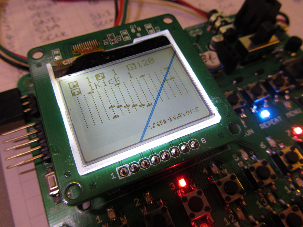
Remember this? It’s all getting a little bit shaky. If you press too hard the board flexes and the PIC resets…
My proto-board prototype was getting quite flaky after lots of use so to move things along I drew up a “proper” layout in Eagle CAD. To give the board a nice finish I used one of Dangerous Prototypes Sick of Beige templates as the footprint. These are a handy starting point for a layout and come complete with corner mounting holes and nice rounded corners. I used the DP10080 template as it’s the largest that fits into the size limits of the free version of Eagle and also within the 100x100mm board size at Seeedstudio.
I wanted to keep the board fairly easy to assemble by hand and use components that are reasonably easy to get hold of. I also wanted to limit myself to using a chips that are also available in DIP format, the same as my prototype. The idea being that if required the board could be re-made as a through-the-hole layout instead of surface mount. So that meant sticking with hand solderable surface mount components, 805s for passives and a SOIC for the PIC. The trickiest part was the MAX6957. The 20 port version of this chip is available only as a DIP or as a fine pitch SSOP. It’s still doable, but a bit of a pain as you will see.
The free version of Eagle has a board size limit of 100x80mm and I needed every millimeter to fit everything in and still have a layout that was reasonably ergonomic. I switched from one row of 16 to two rows of 8 step buttons which helped a lot.
I wish Eagle would increase their free board size to 100x100mm to match the sizes that most cheap board houses offer. It seems such a waste to not be able to use that extra 20mm.
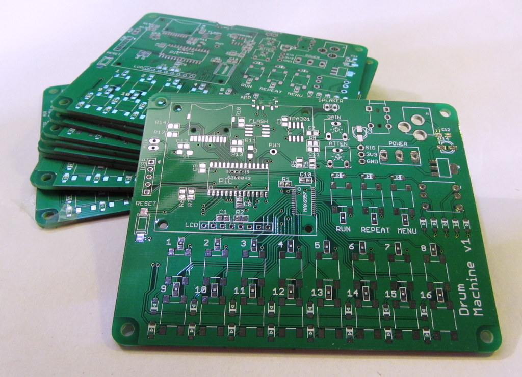
Once I was happy with the layout I sent them off for manufacturing at Seeed and had them in my hands just before Christmas 2012, the plan being to spend some time over the holidays building up a board and trying to get further on with the firmware.
The PCBs came out really well but I did have a few problems with the layout due to oversights on my part. Silly things such as picking a narrow rather than wide package for the MAX6957 LED driver, selecting the wrong drill size for some of the mounting holes and one trace that was just plain wrong… But nothing that couldn’t be fixed with the gentle application of pliers and fine wire.
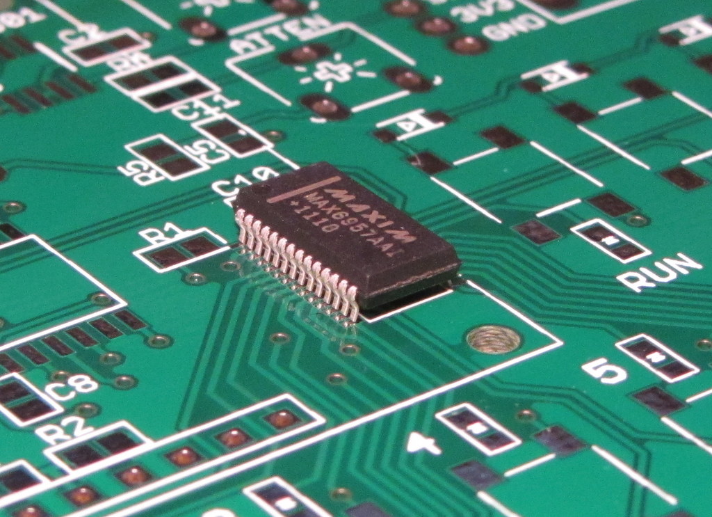
If you bend the pins until they are vertical you can fit a wide SSOP package into a skinny footprint.
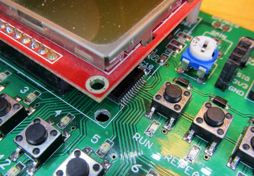
3mm mounting holes on the LCD but only 2mm holes on the PCB. Luckily there’s enough clearance to drill them out.
I managed to get a version of the firmware working with the PIC24HJ128GP502 but was having real trouble trying to make full use of the 128kb of flash. PIC24s have to use some tricks to address all that space, it’s not continuous and you have to specifically tell the compiler where to store large datasets and use special techniques to access the data in blocks of 32Kb. I just couldn’t get my head around it and couldn’t get my code to work with more than a basic drum-kit of audio samples squeezed into a single 32kb block.
Nothing I tried worked and I tried everything I could find including lots of arcane pre-processing pragma things that I really didn’t understand such as declaring all my audio sample data as;
__psv__ signed char __attribute__((space(psv))) kick_1[] ={...}
Bizzare!
I’m sure there’s a correct way of doing this but for the life of me I couldn’t find it and somewhere along the way Microchip released a DIP version of their new 32bit PICs.
These PIC32MX chips are the same price or cheaper than the PIC24s, they’re mostly pin compatible with similar PIC24 parts and you can program them with the Pickit3. Plus they are available in DIP format for easy prototyping. They also have loads of RAM and loads of program flash that can be accessed directly with no special tricks or messing around.
So. I switched to a PIC32. (Specifically a PIC32mx150f128b). It has the same 128kb of program flash as the previous PIC24 but has 32Kb of RAM which gives me a lot of headroom for some new ideas. It also runs at 40Mhz which is great, but the main advantage right now is that I have full access to all the Flash and only have to declare the audio sample data as plain old const signed char, easy!
The conversion for the 16bit to 32bit pic was fairly straightforward, at least at first. I had to sweep my code for variables declared as unsigned int which of course are now all 32 rather than 16bit but other than some expected changes to the device config I had the core “hello world” version of my firmware compiling without errors fairly quickly.
However here’s where RTM comes in to play. Once I started to re-introduce the modules that make use of the PICs peripherals (SPI, UART and CCP) I started to run into problems.
I didn’t realise it but the pic32 series have a much more limited version of Peripheral Pin Select than I was used to with the PIC24. The PIC24s are great in this respect. Whilst you are laying out your board you can alter your periperhal connections for easy PCB routing knowing that PPS will allow you to re-map them to where ever they end up. The PIC32s are not so flexible, they do have PPS but each peripheral can only be connected to a small subset of the re-mappable pins and some functions such as SPI clocks are fixed to specific pins. Not such a big deal if you start out knowing this but quite a pain for me with a circuit board made up for the PIC24!
That required some re-work… More pliers and fine wire.
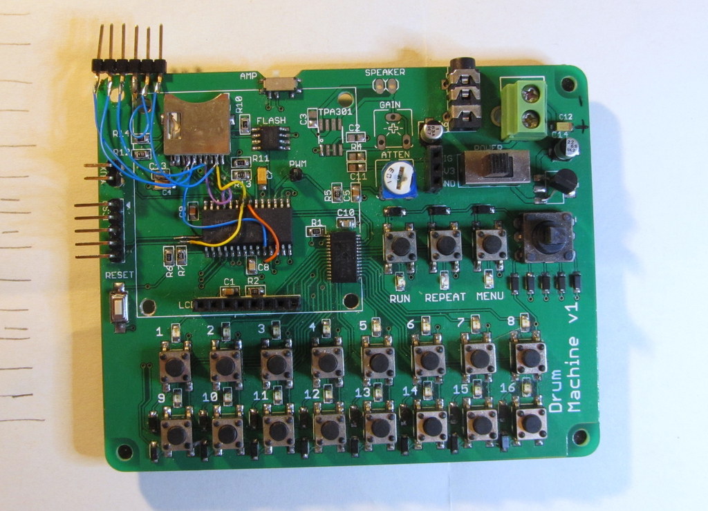
Blimey, that’s a bit of a mess! You don’t want to see the other side… I really should have read the data-sheet before I assumed I could just drop the PIC32 in a PIC24 hole.
So the v1 turned out to need a fair bit of messing about to get it to work well with the pic32. Added to that I was missing decent test/debugging points which was really starting to drive me crazy every time one of those little test probe hook things popped off just because I looked at it wrong.
So after a bit of careful planning and with the one eye on the PPS section of the data-sheet I arrived at version 2 designed specifically with the PIC32 in mind and with lots of extra test points built in for all the signals that I needed to debug such as the the SPI bus with its MOSI, MISO, CLK and all the chip-select lines.
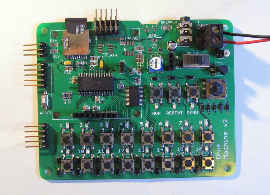
That’s a full row of test points up there. Just look, one for every device on the SPI bus! Can’t say fairer than that!
Even then I managed to screw it up just a little bit with one pad cutting right through another trace on the bottom of the board. It was literally the last thing I did on the board before running the script to produce gerbers at 3am one morning. Luckily the offending pad was only for debugging so a quick snip saves the day.
So there you have it. A new board for a new PIC.
Next it’s the firmware but that’s for a different post.
First of all I must say that this is a hell of a project for one project and you nailed it! Good job!
My question is, would it be possible to place your audio samples on the sd card and use something like the VS1053 decoder and instead of placing the samples in the PIC memory to load then in realtime from the SD Card and “play them” through the decoder? Would this be a good solution for, lets say, edrum modules? Wonder if it could play with minimum delay those samples..problably using an eMMC would be better because of higher transfer rates altough sd card read speed is pretty high,
Best regards!
Glad you like the project.
I have played with the idea of having the samples loaded from the SD card, it’s be a really nice feature, but it runs up against lots of problems in this particular project.
The main problem is in trying to get decent random read speed out of the SD card whilst also sharing the SPI port with the LCD and LED driver. I’m currently running all access to the SPI port in the main() line of the program. I’d need to run the SD card access using interrupts and DMA in order to get enough speed and this makes life much more difficult especially as the LCD uses a 9-bit format that couldn’t be converted over to DMA (as far as I know.) so you’d need to arbitrate between the SD card runing with DMA and the other devices… Plus it’s not just the speed of the SPI port, but also the overhead of the FAT file-system this adds complexity and also a lot of RAM requirements to keep 16 files open ready for random access.
I have played with the idea of using a 4mb SPI Dataflash as a sample store (I even have a footprint for it in my current board). The idea being that on boot the program copies the necessary samples from the SD card into the Dataflash, each at known memory location. The advantage being that the program doesn’t need to use FAT or any of that stuff, it just accesses the data directly from a known address for a known length. This sort of works, but again the problem is sharing the same SPI port with the other devices whilst trying to get enough speed out of the thing.
On paper I’ve played with the idea of a caching scheme that tries to ensure that the next sample for each instrument is always ready in a buffer in the PICs RAM, loading the buffers in the background. Possible, but again much more complex that having the samples in Prog-Flash where they are readily available with no delays.
You could solve this by using a different PIC, one with more pins, that way you could dedicate an SPI port to just the SD card (or Dataflash). That would give you speed and access it using DMA with no worries about sharing it with other devices.
That’s beyond where I want to go with the project at the moment. In order to keep this project more DIY-able I purposely chose to limit it to chips that are available in easy to use DIP format. This limits the number of GPIO and peripherals available on the PIC so rules out the idea of a dedicated SPI port for sample access.
Anyway. It’d be a great feature, but so far not one that I’ve come up with a solution for.
Cheers.
Matt
Matt, I’m truly thankful for your answer! I’m not quite (yet) ready for this type of projects, lots of work and study hours are to come!
Related to polyphony with sounds coming from a sd card and an external codec chip do you believe that a dspic would be able to handle it or should I just simply jump up for something like the parallax microcontroller that is 32bit and multicore or maybe a teensy 3.1?
And what about the capability to immediately play one or more sounds when we press,let’s say, one or more buttons?
Sorry to throw off this questions at you.
Regards,
João Gonçalves.
Hi João,
No problem, glad to help if I can.
—
The answer depends on various things, the quality of the sounds, how many, and what else the MCU has to do at the same time eg. display output on an LCD.
If you store the audio in a simple format on the SD card then reading it out any playing back is a really simple task that almost any MCU can handle.
Probably the simplest audio format to use is 8bit PCM mono. You could adjust your sample rate to suit your needs. Higher sample rate sounds better but involves more data transfer. 8khz 8bit is pretty crappy, but can sound ok for spoken word and sound effects. 8bit at 16khz can sound ok for music (not great but ok). You could also use uLaw/aLaw compression to improve the dynamic range of the samples for better quality output.
If you want to use MP3’s then you do need something more powerfull or a codec chip that can handle playing multiple streams.
But assuming you keep it simple;
If you want to polyphony then I guess it depends on how many concurrant sounds you want to play, what quality they are and also what else your application needs to do.
A PIC32 like I’m using (or something similar) should easily be able to play multiple concurrent 8bit WAVs direct from the SD card when you press a button. (3 or 4, probably more, I’ve not tried it). Put the SD on it’s own SPI port and use a high speed (20Mhz or something)
Best way to find out is to try it!
:o)
I LOVE it!….but. How do I use this like an edrum set instead of a drum machine? Are you selling these? Would you be able to / willing to modify one of your boards accept inputs from piezos….possibly with this in between the piezos and your board. http://www.spikenzielabs.com/Catalog/index.php?main_page=product_info&cPath=17&products_id=55 . I’m dying to find a way to make a super portable edrum set so I can play where ever I go. So far the best I’ve done is take my yamaha dtxpress III drum module and hook up my own set of piezos to it. Better than the full size set but the drum module is still bulky =(. Man if I had your mini module for my drums set brain I’d be in heaven. I’m willing to pay for your parts or time. Not looking for charity. Just looking to solve my problem =).
Cheers,
Will
[I removed your phone number]
Hi Will,
I don’t really know much about edrums but I’m gussing that the idea is that to have something with multiple pressure sensitive pads that you can play with sticks like a real drumkit no? To do that I’d you’d want to have analog inputs so you could read the difference between a slight tap and a solid whach in order to play the sample at the appropriate volume. That’d be problematic to fit into how the project is built. It’s already using all but 1 of the available GPIO and many are muliplexed to support multiple inputs. This means that there aren’t really any free pins left to use as analogue inputs for a drum kit. Also internally the sequencer only records a binary state for each beat, the sample is played or not, there’s no variable volume control for each beat.
I’m afraid that it comes down to the the fact that this project isn’t really set up to work as an e-drum, it really is built to be a sequencer.
You could certainly use some of it as a starting point, maybe using a larger PIC with more pins to alow analogue inputs but that’s beyond what I want to do with it right now. I simply don’t have the time, sorry.
If you’re interested in taking it further yourself I’m happy to share the source code with you, I can even send you a bare PCB to get you started.
Regards
Matt Casey
Hi! Can I buy one of these little drum machines? I would be awesome 🙂
Hi Rafael. At the moment I have no plans to sell these. I you’d like I can send you a PCB and you can assemble one yourself.
Thanks! I really don’t know about electronics, but if I feel like trying I’ll drop you a line. Thanks!
Hello. I whant to buy one pcb or the gerbers files to make a drum machine.Also I needt the hex file to programming the PIC. How much is the pcb and the pic with program inside?
Best Regard,
Alex
Hi, great project, just my sort of thing
I’ve done a lot of audio work with the dsPIC and SDHC. Some of this involves reading .WAV sound samples from the card(s). A problem has come up due to Read Disturb, which causes the PIC to not be able to complete a Block Read. It’ll happen in my application after several 100,000 reads. Which sounds a lot, but if you work that out as the same drum being played repeatedly that number could be reached sooner than you expect. For example at 180bpm, there’s 10,800 reads an hour of the same file. If the power is cycled then my application will run again, but it’s a very much shorter time until another read fail. One option then is to reformat the card, others involve refreshing the card blocks from an SRAM buffer or another SDHC card (then you have to consider the working card’s Write Endurance) or having multiple copies of the file on the card and an access management system.
Sandisk have a pdf covering the Read Disturb issue, and others
Click to access WP001_Flash_Management_Final_FINAL.pdf
As they note, as cell sizes get smaller (ie more and more GB on a card) the problem is exacerbated. For now I’m sticking with 4GB and 8GB and avoiding “inferior” brands which may be poor quality or even counterfeits to a greater or lesser degree
Just a heads up, perhaps it’ll save you (some of) the headaches I had
best regards, Joe
Hi Joe,
That’s a great coment. Thank you for taking the time to write it.
I’m happy to say I’ve not come across the Read Disturb issue. Probably because I’m not reading that much from the SD, certainly nothing like the amount of reads you describe. It might also be because all the SD cards I’ve been using are in the 64 to 256Mb range (scavanged from old electronics) so probably have much larger blocks.
It’s really useful to know though as I keep toying with the idea of having the samples on the SD and either streaming them direct off the card or pulling them into a SRAM on boot. Both of which might run me up against this issue.
Thanks again.
Matt
Hi Matt,
no problem passing that info on. It’s not a widely-known issue, as I found out the hard way. It’s not just restricted to data files, because if you use any sort of FAT system the boot sector and directory have to be read, and more often than individual files. That’s what I’m currently using but plan to change to absolute block addressing to avoid Read Disturb failures in the card’s O/S
Yeah, the smaller cards, MMC, < 4GB etc, are getting harder to get hold of now, around here anyway, and that's not going to get any better as devices like phones and solid state drives demand bigger capacity memories. And it's not like they're long-lived devices, most are going to end up in the trash in a few years. Manufacturers may quote 40 or 100 year data retention but, seriously, does anyone expect to have the same phone in 2056 ? Or even 2018 ?
Anyhoo, end rant, unfortunately I can't use SRAM for the problem app, as the files total 700MB. They're 44.1kHz 16-bit stereo (although the dsPIC DAC isn't quite that good) so I need a moderately large card.
They're "real life" sounds so I'm not using any synthesis, eg PWM like you're doing. I've been impressed by the implementations of Karplus-Strong algorithms, such as the Harpie (Google harpie dspic) to create very interesting musical tones.
For a couple of circuits I can use a 512kB SRAM and play small copied files from it, as you mentioned. That does drastically reduce the number of times the card is read.
One of those circuits (actually a non-card circuit) is a dsPIC digital delay/flanger/(pitch changer ?) I'm working on as part of a synthesiser restoration. Hopefully it'll be a cheap and effective module with a better dynamic range than the bucket brigade ICs.
I'm all about sequencers at the moment, upgrading my old analogue/logic ones to have some PIC content, for triggering synchronisation, arpeggios, rhythm inputs etc. When I get a bit further down the track we should swap notes.
wbr Joe
Hi Joe,
I hadn’t thought about the impact FAT would have. You’re right. I might not be making many reads requests to the file system but it would be making many more to the SD card on my behalf. I’m using FatFs but like I say, so far no problems.
Thanks for the harpie dspic tip. Those are some nice projects. At one point in the past I wrote an Karplus Strong Implementation – I think for PIC24, not that I can find the code now – That was what got me started on the Drum Machine. I was looking at trying to synthesise the drum sounds but in the end I went with samples for simplicity sake.
If you’re interested I have my Drum Machine project (Source and Circuit) up on Github. It’s not award winning C programming or anything… but it works.
At this point I must admit that I’m not actually very “musical” whatever that might mean. No talent – not like my brother – just fascinated by being able to create sounds and love drum machines for some reason I can’t quite explain.
Cheers,
Matt
Hi Matt,
one of my sub-projects in the synth restoration is a drum sequencer, based on the “Master Rhythm” circuit from the Jan ’81 issue of Practical Electronics (UK). I made one at the time, which I still have, and it worked very well. Time has not been kind (poorly stored) and it needs repairs. Fortunately I still have the magazine for reference. I’m going to replace the original digital part – which was basically pushbuttons, a little logic and a small SRAM to store the pattern – with a PIC and use home-made piezo pads for alternate inputs. The analogue section is very simple and generates drum and percussion sounds from a white noise source and damped oscillators. The data pin outputs of the SRAM are the triggers, which can also be run off to note sequencers, envelope shapers etc. PM me if you want the schematics and/or complete article.
wbr Joe
Hi Matt,
I realize this was a long time ago but do you have any pcbs left for sale? Been thinking about doing exactly this as my latest project.
Best regards,
Luan
hi Matt,
can you send me the pcb schematic of this project?
Hi Charith,
Code and schematics are here.
https://github.com/Catmacey/DrumMachine
Hello, great project you made for my admiration. I repeated the project for a drum machine but I would like if I could have on it the latest software which I saw on a video clip, with the possibility of menus and reverb. Would you be so kind as to send me this code so I can enjoy my new machine.
With exceptional thanks for the wonderful project.
Respectfully
Hi Dark.
That’s fantastic. It’s great to hear that you built your own. Do you have photos, a blog post or something? I’d love to see it.
Regarding the firmware. Is it the v2 – PIC32mx150f128b project that you built?
I haven’t worked on that version for a while now but I’ll have a dig around in my repo for a more recent build than is published and get that updated onto Github.
Hi Dark,
I have updated my GitHub repo with the latest stable code for this version.
It’s got some new features, Jam mode, Tuning, Swing and Reverb.
Hello! I am electronics engineer and DIY (and, product of 80ies, i might add), and I recently got itch again about music instruments 🙂
I imagine, maybe you have some blank PCB left that i could get for some adequate fee? I live in Latvia (EU), but shouldn’t matter, PCB can be sent easily in envelope, I guess 🙂 I would really appreciate. Thank You in advance.
Juris.